GB - 25
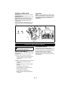
2. Turn the adjustment barrel up the cable to
decrease the distance between clutch
lever and handlebar.
Turn the adjustment barrel down the cable
to increase the distance between clutch
lever and handlebar.
3. Check traction clutch lever distance and
repeat adjustment steps if necessary.
4. Tighten jam nut on traction cable
adjustment barrel.
FRICTION DISC REPLACEMENT
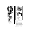
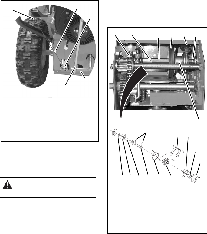
Remove (Figure 22 and 23)
1. Shut off engine, remove key, disconnect
spark plug wire, and allow unit to cool
completely.
2. Place unit on a level surface and tip unit up
onto front housing.
3. Remove wheels.
4. Remove bottom cover.
5. Disconnect shift rod from speed selector
arm.
6. Carefully tap roll pins out of hex shaft.
7. Remove outside bearing flange and
bearing from each side of unit.
8. Remove friction disc from shift carrier.
9. Remove roller chain from sprocket on hex
shaft.
10. Remove spacer from hex shaft.
11. Hold shift carrier and slide hex shaft slowly
to the right.
12. Slide shaft only far enough to remove the
old friction disc from hex shaft.
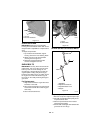
Install (Figure 22 and 23)
1. Place flat side of new friction disc against
shift carrier.
2. Hold shift carrier, slide hex shaft back
toward the left through roller chain and
spacer, and through the opening in the
side of the unit.
3. Install roller chain on sprocket teeth of hex
shaft.
4. Install bearings and outside bearing
flanges.
CAUTION: Remove fuel from fuel
tank prior to placing unit in service
position.
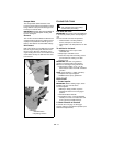
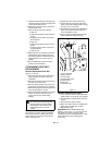
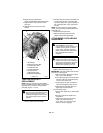
Figure 22
1. Traction Clutch Cable
2. Adjustment Barrel
3. Jam Nut
4. Speed Selector Arm
5.Shift Rod
OS6825
4
5
1
2
3
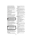
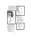
Figure 23
OS5000
1. Roller Chain
2. Roll pin
3. Hex Shaft
4. Friction Disc
5. Speed Fork
6. Shift Carrier
7. Outside Bearing
Flange
8. Ball Bearing
9. Inside Bearing
Flange
10.Spacer
1
2
3
4
5
6
7
8
9
5
6
4
3
10
9
8
7
2
2


