


GB - 25
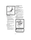
TRACTION DRIVE CLUTCH
ADJUSTMENT
If drive slips, adjust traction clutch to
compensate for friction disc wear.
To adjust traction clutch:
1. Place speed selector in First (1) Forward.
2. Place unit in service position.
3. With traction clutch disengaged and
locking differential engaged (on
applicable models) turn wheels while
tightening adjustment nut at clutch yoke
(Figure 21).
4. Engage and release traction clutch.
5. Turn wheels to check for slight drag.
6. Repeat steps 3 - 5 until wheels begin to
drag.
7. Turn adjustment nut back three turns.
Wheels will then turn freely.
DRIVE CHAIN
Chain should be taut with little or no play in it.
To compensate for looseness or excessive
tightness in drive chain:
1. Put unit into service position.
2. Remove bottom cover by removing four
cap screws.
3. Loosen nuts on idler hex shaft
(Figure 25). Adjust the idler hex shaft in
slot as necessary. Torque the nut to
70-146 lbf-in. (7.9 - 16.5 N•m).
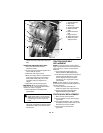
ATTACHMENT DRIVE BELT
REPLACEMENT
Remove old attachment drive belt:
1. Shut off engine and allow to cool
completely.
2. Remove belt cover (Figure 23).
3. Remove spring clip from chute crank to
remove chute crank.
IMPORTANT: Disconnect remote cap
deflector and/or electric chute wire harness (if
equipped) before proceeding.
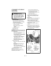
4. Loosen cap screws and carefully rotate
belt fingers away from belt and sheave
(Figure 24).
IMPORTANT: Use care when rotating the belt
fingers. DO NOT bend belt fingers out of
shape.
5. Remove attachment drive belt from engine
sheave (it may be necessary to turn
engine sheave using recoil starter
handle).
IMPORTANT: To avoid bending bottom cover
when tipping unit apart, support handlebars
firmly or tip unit up on housing and remove
bottom cover by removing four cap screws
before separating unit.
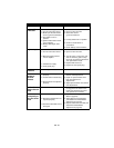
6. Support Sno-Thro frame and housing.
7. Remove cap screws securing housing to
frame (one on each side). Tip housing
and frame apart on pivot pins (Figure 23).
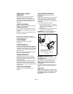
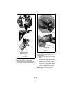
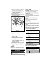
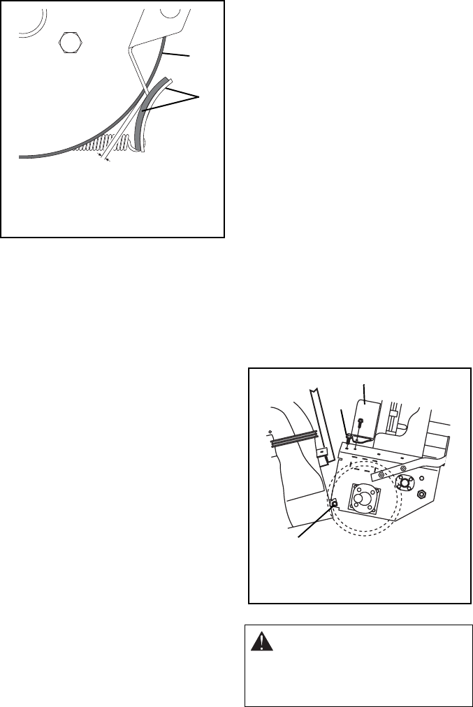
Figure 22
1
2
1.Drive Belt
2.Brake Shoe and Pad
OS0660
Minimum of 1/16 in. (1.6 mm)
CAUTION: Always support Sno-Thro
frame and blower housing when
loosening the cap screws holding
them together. Never loosen cap
screws while unit is in service
position.
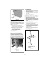
Figure 23
1.Pivot Pin
2.Housing Cap Screws
3.Belt Cover
1
2
3
OS0792