


GB - 24
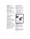
ATTACHMENT CLUTCH/BRAKE
ADJUSTMENT
(Figures 21 and 22)
1. Remove belt cover.
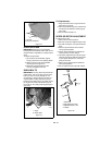
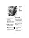
2. Check belt alignment (Figure 24).
Engine sheave and attachment pulley
must align vertically. Also, belt must be
centered in the idler pulley.
To align, move attachment pulley:
a.Loosen set screws.
b.Slide pulley and key to desired
position.
c.Tighten set screws.
3. Install belt cover.
4. Adjust cable slack.
IMPORTANT: The belt cover must be installed
and the clutch cable must be slack when the
lever is disengaged.
a.With clutch lever disengaged, loosen
jam nut on cable adjuster.
b.Turn adjuster body to remove all slack
from the cable. Do not stretch spring
or move lower clutch arm.
c.Turn back the adjuster body 5 turns
(approximately 1/4 in. or 6 mm).
Finger tighten jam nut.
d.Hold adjuster body with pliers and
tighten jam nut with wrench.
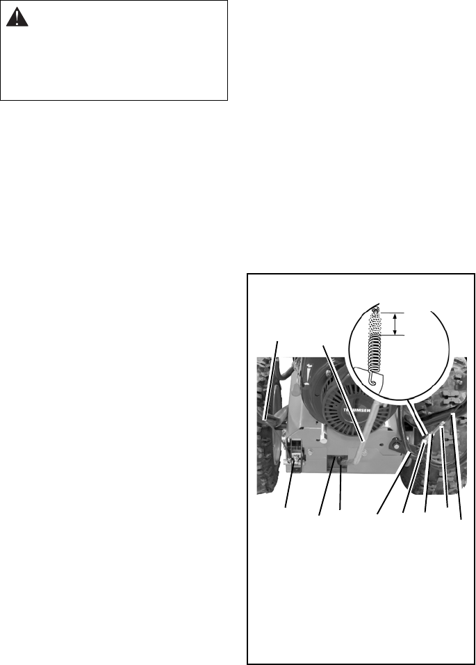
5. Check spring length.
a.Measure the length of the clutch cable
spring.
b.Engage and hold the attachment
clutch lever.
c.Measure the length of the spring
again. The spring should be
7/16 –11/16 in. (11.1–17.5 mm) longer
when the lever is engaged.
6. Adjust spring length.
NOTE: Approximately 1/8 in. (3 mm)
movement of the idler will change spring
extension by 1/8 in. (3 mm).
a.Loosen the idler adjustment nut.
b.To increase spring extension, move
idler towards belt (Figure 24).
c.To decrease spring extension, move
idler away from belt.
d.Tighten idler adjustment nut.
7. Place unit in service position. Remove
bottom cover by removing four cap
screws.
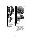
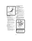
8. Check brake.
When the clutch lever is disengaged, the
brake must contact attachment belt.
When the clutch lever is engaged, the
brake must be more than 1/16 in.
(1.6 mm) away from the belt (Figure 22).
9. Repeat steps 4 – 7 until:
Spring stretch and brake contact are
correct.
10. Check belt finger clearance (Figure 24).
With clutch lever engaged, belt fingers
should be 1/16 – 1/8 in. (1.6 –3 mm) from
belt. Adjust belt fingers as necessary.
11. Replace bottom cover.
IMPORTANT: IMPROPER
ADJUSTMENT could result in
unexpected movement of auger and
impeller causing death or serious
injury. Auger / impeller must stop
within 5 seconds when Attachment
Clutch/Impeller Brake lever is
released.
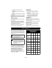
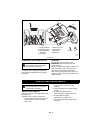
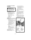
2
1
3
4
5
6
OS3040
Figure 21
7
8
9
7/16–11/16 in
10
1.Attachment
Clutch Cable
2.Cable Adjuster
3.Jam Nut
4.Clutch Cable
Spring
5.Lower Clutch Arm
6.Shift Arm
7.Cotter Pin and
Washer
8.Adjustment Nut
9.Traction Drive
Clutch Cable
10.Shift Rod
(11.1-17.5 mm)