


GB - 27
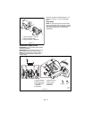
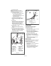
8. Remove cap screws securing housing to
frame (one on each side). Tip housing
and frame apart on pivot pins (Figure 20).
9. Remove attachment drive belt from
attachment pulley (hold brake away from
belt).
Install new attachment drive belt:
1. Place new attachment belt onto
attachment pulley.
2. Tip housing and frame back together and
secure with cap screws.
3. Place belt onto engine sheave.
4. Make sure engine sheave and attachment
pulley align. If alignment is necessary,
loosen attachment pulley set screws,
reposition pulley and retighten set screws.
5. Reposition and secure belt fingers.
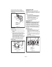
IMPORTANT: Make sure belt fingers are
1/16 in. to 1/8 in. (1.6-3mm) from belt when
attachment clutch is engaged.
6. Check adjustment. See Attachment
Clutch/Brake.
7. Reconnect chute crank and secure with
spring clip. If equipped, reconnect remote
cap deflector cable and/or electric chute
wire harness.
8. Replace belt cover.
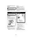
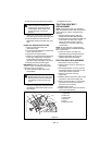
TRACTION DRIVE BELT
REPLACEMENT
NOTE: Housing and frame must be tipped
apart and attachment drive belt removed from
engine sheave in order to change traction
drive belt.
1. Remove attachment drive belt (see
Attachment Drive Belt Replacement).
2. Pull idler away from traction drive belt and
remove belt from idler pulley, engine
sheave and driven pulley (it may be
necessary to turn engine pulley using
recoil handle).
NOTE: To gain clearance, engage traction
clutch and if necessary pull back attachment
idler arm clevis pin.
3. Install new traction drive belt onto
attachment pulley and engine sheaves.
4. Replace attachment drive belt (See
Replace Attachment Drive Belt).
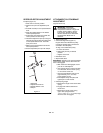
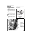
FRICTION DISC REPLACEMENT
1. Place unit into service position.
2. Remove bottom cover by removing four
cap screws.
3. Place speed selector in first (1) position
and depress traction clutch lever to hold
friction disc and hub in position.
4. Remove cap screws from hub
(Figure 22).
5. Release traction clutch lever, shift to third
(3) position, and remove friction disc.
6. Secure new friction disc on hub with five
cap screws and torque cap screws to
8-10 lbf-ft (10,6-13,3 N•m).
7. Replace bottom cover.
8. Adjust traction drive clutch (see Traction
Drive Clutch Adjustment).
CAUTION: Always support Sno-Thro
frame and blower housing when
loosening the cap screws holding
them together. Never loosen cap
screws while unit is in service
position.
WARNING: AUGER / IMPELLER
MUST STOP within 5 seconds when
attachment clutch lever is released or
unit damage or serious injury may
result.
1
2
3
4
5
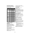
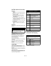
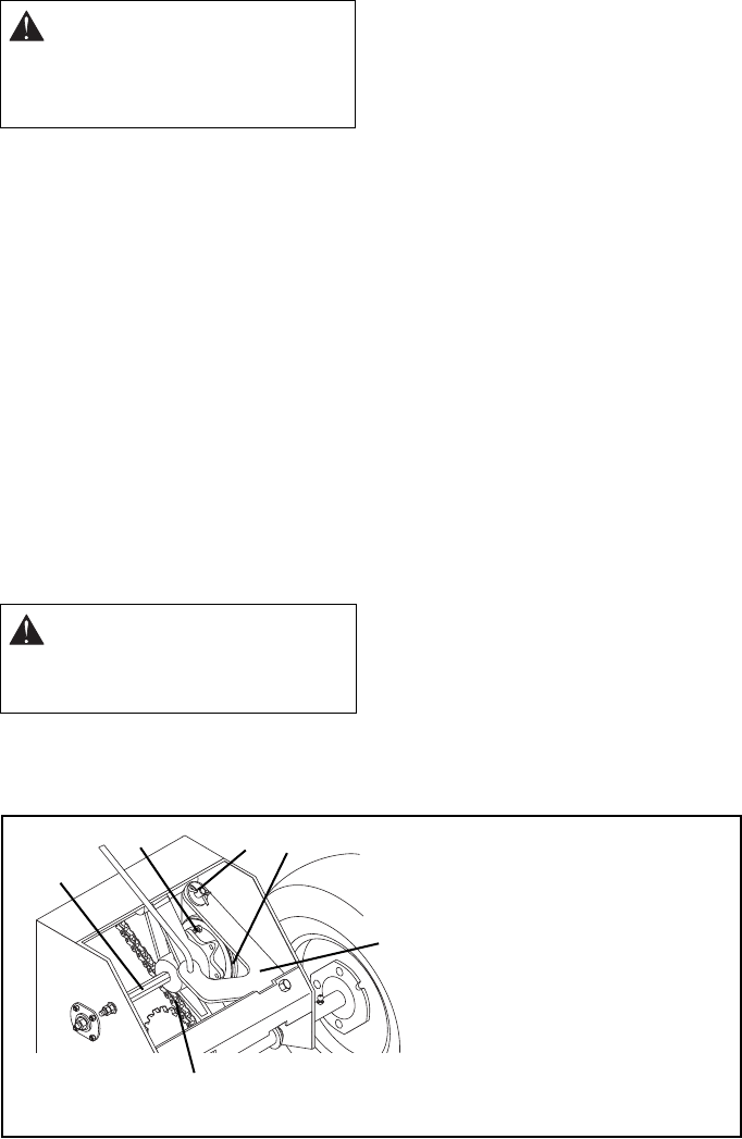
Figure 22
6
OS0612
1.Cap Screw
2.Cotter Pin
3.Friction Disc
4.Shift Arm
5.Chain
6.Idler Hex Shaft