


GB - 16
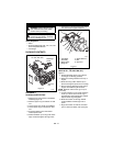
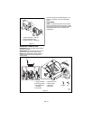
Discharge Chute Deflector
ALWAYS position discharge chute deflector at
a safe angle before starting engine.
DO NOT throw snow any higher than
necessary.
Push deflector handle forward or down to
throw snow lower. Pull deflector handle up or
to the rear to throw snow higher.
IMPORTANT: If Chute Deflector does not stay
in set position, adjust as directed in Service
and Adjustments, or repair before operation.
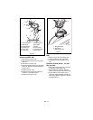
Deflector Remote (924121, 332, 505,
506)
Place deflector into position before operation.
DO NOT throw snow any higher than
necessary.
Push deflector remote forward to throw snow
lower. Pull deflector remote back to throw
snow higher.
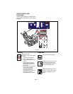
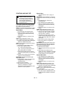
Discharge Chute
Discharge chute rotates 220°.
ALWAYS position discharge chute in safe
direction and angle, away from operator and
bystanders, before starting engine.
Chute Crank (924121, 122, 332, 508)
IMPORTANT: If chute does not stay in set
position, adjust as directed in Service and
Adjustments, or repair before operation.
Rotate the Chute with Discharge Chute Crank
Handle.
IMPORTANT: DO NOT force frozen chute
controls. Start engine and run for 3-5 minutes
to thaw. If still frozen, take to warm place until
controls are free.
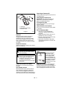
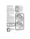
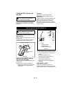
Chute Rotation Switch (924505, 506)
Press the chute rotation switch right (1) to
rotate chute clockwise. Press the chute
rotation switch left (2) to rotate chute
counterclockwise.
Heated Handles
Turn the heated handles
switch to the ON (1) position
to activate. Turn the switch
to the OFF (2) position to
deactivate.
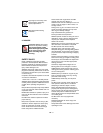
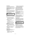
Differential Lock (924118, 122, 332,
505, 506, 508, 551)
Differential Lock knob is located
on the Left Wheel Hub. With
differential locked power is
applied equally to both wheels.
To engage differential lock:
• Pull and turn knob to LOCKED
(1) position and release (knob
will snap in place when
positioned correctly).
To resume differential action for
transport:
• Pull and turn knob to UNLOCKED (2)
position and release.
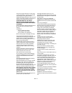
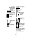
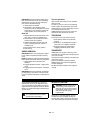
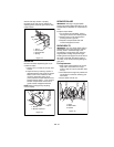
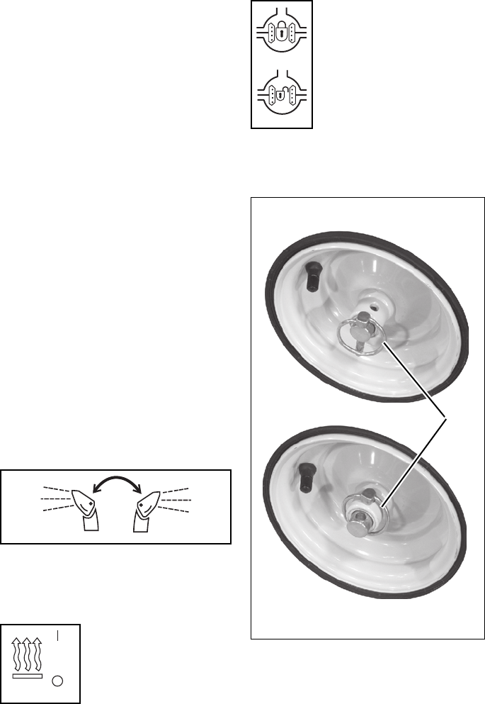
Axle Lock Pin (Figure 9) (924121)
Use the axle lock pin to lock or unlock the right
wheel. Lock the right wheel to increase
traction; unlock the right wheel to allow for
easier turning of the unit.
OS1970
12
OS1950
1
2
1
2
OL2730
Figure 9
Wheel Unlocked
Wheel Locked
Axle
Lock
Pin