GB - 14
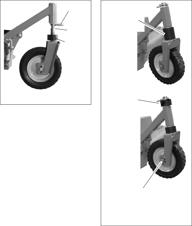
Align the open ends of the spacers with the
flats on the caster spindle and remove the
spacers one at a time until enough are left at
the bottom for the desired cutting height.
Remove the lock pin while supporting the
caster arm. Lower the arm on top of the
remaining spacers. Put the spacers that were
removed in the caster spindle above the
support tube as shown (Figure 8).
Reinstall the lock pin into the top hole and flip
over the lock ring to secure the remaining
spacers and pin.
NOTE: Set both wheels at the same height
for a level cut.
Figure 7
Spacers
Lock Pin
Flats
Figure 8
Remove the
spacers from
the stack.
Secure spacers
above the
caster arm with
the lock pin.
NOTE: Axle positions are set at the
factory. There should be no need to
change the axle position in the caster
in normal use or maintenance.


