GB - 19
CHECK SPARK PLUG
Spark plug should be replaced every 100
hours of operation or each year.
NOTE: Loose spark plug wire terminals can
cause sparking. Replace terminal if
damaged.
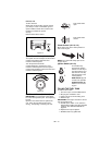
CHECK ENGINE COOLING
To prevent overheating, air must circulate
freely around the cooling fins, cylinder head
and block.
Every 100 hours of operation or yearly (more
often if conditions require) remove blower
housing and clean cooling fins. See engine
manual for instructions.
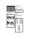
CHECK MUFFLER
Check muffler for debris, cracks, wear, or
other damage.
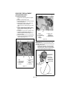
SERVICE POSITION
Put unit into service position for easy access
to underneath the deck.
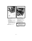
1. Place unit on a flat, level surface.
2. Disconnect spark plug wire from spark
plug.
3. Remove fuel cap, place a piece of
plastic bag over the opening and tighten
cap securely.
4. Tip unit onto right side (911112, 113).
Tip unit onto left side, opposite the
discharge opening (911110, 111).
Make sure unit is secure and will not tip
over.
IMPORTANT: Remove plastic from fuel cap
after unit is upright and service is complete.
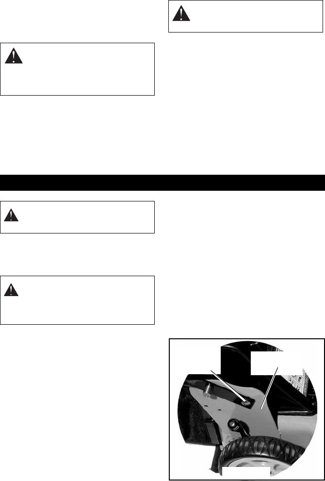
HANDLEBAR HEIGHT
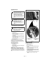
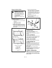
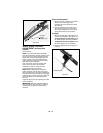
To adjust (Figure 16):
1. Remove hardware from lower handlebar
mounting hole.
2. Rotate the handlebar up or down to the
desired height and align the mounting
holes with the holes in the handlebar
upright.
3. Secure the handlebars in position with
hardware removed in step 1.
NOTE: To fold handlebars flat for storage,
remove the hardware from the lower
handlebar mounting holes, rotate the
handlebars forward, and then replace the
hardware in the holes on the handlebar
upright.
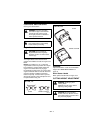
WARNING: HOT SURFACES can
cause death or serious injury. DO
NOT TOUCH parts which are hot
from operation. ALWAYS allow
parts to cool.
CAUTION: Replace worn-out
mufflers immediately. Continued
use could result in fire or explosion.
SERVICE AND ADJUSTMENTS
CAUTION: AVOID INJURY. Read
and understand the entire Safety
section before proceeding.
CAUTION: Avoid fuel spills. Follow
steps below to help prevent fuel
spills. If fuel leaks into air cleaner,
replace air cleaner. ALWAYS clean
up any spilled fuel.
Mounting
Hardware
Handlebar Upright
Figure 16


