


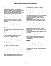

NOTE: Read the tractor and attachment(s) manuals
before operating the equipment. Operate the tractor
only from the operator’s position on the seat. Service
the tractor and attachment before operating.
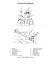
Direction Control Pedal
The direction control pedal controls the
movement of the tractor. Push the pedal
forward and lock over center to go forward.
Push the pedal back to move the tractor
backwards (Figure 1).
Range Selector
The range selector has two operating positions. The
forward (“HIGH”) position is the fast gear. The
rearward (“LOW”) position is the slow gear (Figure 1).
Throttle Control
The throttle lever (Figure 1) is used to
control the engine speed. To increase the
engine speed, move the lever up to the
“FAST” position. To decrease the engine
speed, move the lever down to the
“SLOW” position.
Choke Control
The choke control is used to choke a cold
engine for starting. The choke control is
located on the instrument panel (Figure 1).
Pull the choke out to the “ON” position to
choke the engine. When the engine is warm, move
the control to the “OFF” position.
Hourmeter
The hourmeter (on some models) shows total time
which the ignition switch has been in the “ON”
position (Figure 1).
Fuse
All models have a fuse to protect the electrical
system. The fuse is located in the wire harness.
Ignition Switch
The ignition switch is operated with a
removable key. The switch has three
positions: “Off”, “On” and “Start”.
To start the engine, the key must be in the
“Start” position. Once the engine has started release
the key and it will return to the run position. To stop
the engine, turn the key to the “Off” position.
Gear Selector
The gear selector has four operating
positions (Figure 1). See specifications for
ground speeds produced in each gear.
Attachment Lift Switch
(Hydraulic Model)
The attachment lift switch is used to raise
and lower the attachment. The lift switch is
located on the instrument panel. Move the switch up
to raise, and down to lower the attachment.
Ammeter
The ammeter indicates the condition of the charging
system. Normal operation will show the indicator
needle slightly to the “Plus” side of zero.
Brake Pedal
Pushing the brake pedal down will stop the tractor
and return the direction control pedal to “NEUTRAL”.
Use the brake pedal for sudden stops and for holding
the tractor on slopes.
Brake Lock Lever
To lock the brake for parking, depress the
brake pedal and pull back on the brake
lock lever. To release, push on the pedal
and move the lock lever forward.
PTO Control
To power an attachment, push the PTO
control forward to “ON”. To stop an
attachment, pull the PTO control rearward
to “OFF”. The operator must be in the
tractor seat to operate the PTO. If the operator
leaves the seat while the PTO control is in the “ON”
position, the engine will stop.
Warning Light
The tractor is equipped with a warning light to alert
the operator in the event there is a problem with the
engine. The warning light is located on the upper left
side of the instrument panel. See Figure 1.
6
Operation
STOP
START
RUN
ON
OFF
LOCK
UNLOCK
STOP
GO
3
1
4
2
N
DOWN
UP
HOLD
N
N
FORWARD
REVERSE