


• Turn the control rod to change the free travel. Each
turn will change it by about .25 inch.Turn clockwise
to increase and counterclockwise to decrease the
free travel.
• Reconnect the control rod to the transmission lever.
Check for correct free travel. Repeat above three
steps if necessary.
• Put the PTO control in the “Off” position.
• Move the switch bracket up until the switch closes
(makes a circuit). Tighten the switch bracket
hardware.
CAUTION: Make sure that the PTO
control assembly does not rest on the
switch body.
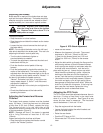
Adjusting the Steering System
Adjustment of the steering gear is usually needed
whenever there is more than 2 inches of free play in
the steering wheel. To adjust the steering gear:
• Loosen the lock nuts on both adjusting bolts
(Figure 4).
• Turn the steering wheel to the right as far as it will
go.
• Turn the adjusting nut on the left side adjusting bolt
clockwise with your fingers until it is tight.Then
back the nut off one fourth turn.
• Tighten the lock nut against the adjusting nut being
careful not to move the adjusting nut.
• Turn the steering wheel to the left as far as it will
go.
• Repeat the above two steps for the right side
adjusting nut.
• Check for tightness or backlash in the steering gear
through the full range of the steering wheel rotation.
There should be no noticeable tightness or
backlash in the rack and pinion mesh. If there is,
repeat above steps as required.
Upon completion of the steering gear adjustment,
recheck the steering wheel free play. If the free play
is still excessive, look for loose steering arms on the
king pins, loose or worn ball joints, or other signs of
wear. Tighten or replace as required.
Adjust the front wheel toe-in as follows:
• Rotate the steering wheel until the two steering arm
weldments are parallel to the frame side.
• On 13.5 HP and 16 HP engine units, loosen the
jam nuts on the tie rods and disconnect the outside
ball joint. Rotate the front tires by hand so that the
distance between the front centerline of the tire is
1/8” to 1/2” less than the Distance between the rear
centerline. Adjust the tie rods so that the ball joint
can be connected to the tie rod arm without moving
the tire and so that the tie rods are the same length.
Tighten the jam nuts.
• On 20.5 HP units, loosen the jam nuts on the
tie rods and rotate the tire rod tube so that the front
centerline of the tire is 1/8” to 1/2” closer than the
rear centerline and so that the tie rods are the
same length.Tighten the jam nuts.
Servicing the Spark Plug(s)
To clean or change a spark plug:
• Stop the engine, lock the brake, and raise the seat
pan weldment.
• See your engine manual for further instructions.
Servicing the Hydraulic Lift
WARNING: Keep body and hands away
from pin holes or nozzles which eject
hydraulic fluid under pressure. Use
paper or cardboard and not hands to
search for leaks.
Be sure to stop the engine and put the attachment in
the down position before doing any work on hydraulic
parts.
WARNING: Make sure all hydraulic fluid
connections are tight and all hydraulic
hoses and lines are in good condition
before applying pressure to the system.
Hydraulic fluid escaping under pressure may have
sufficient force to penetrate skin and cause serious
injury. Foreign fluid injected into the skin must be
surgically removed within a few hours by a doctor
familiar with this form of injury or gangrene may
result.
Check the hydraulic fluid level when the hydraulic lift
will not raise the attachment or leaks are observed.
To check the hydraulic fluid level:
• Clean the area around the reservoir and cap.
• Remove the cap.
• The correct hydraulic fluid level is one inch from the
top of the reservoir. Add Dextron II ATF to maintain
this level.
Adjustments (Continued)
13