


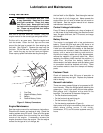

Adjusting the Brakes
Brake service is required if the brake does not stop
and hold the tractor effectively. The brake should be
effective enough to cause the rear wheels to slide if
applied suddenly on a concrete or asphalt surface.
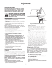
CAUTION: Replace the brake band
when the lining is as thin as the ignition
key. Replace the brake drum if it is
visibly worn or rough.
To adjust the brake:
• Stop the tractor on a level surface.
• Stop the engine and block the wheels so the tractor
cannot roll.
• Loosen the jam nut and remove the clevis pin (at
the brake band)
NOTE: Do not adjust the brake rod on the left hand
side which attaches to the brake pedal. This rod is for
adjusting the direction control pedal only.
• Turn the clevis clockwise to tighten or
counterclockwise as needed.
• To check the adjustment, reconnect the clevis and
brake band with the pin.
• Push the direction control pedal all the way
forward.
• Push the brake pedal by hand while watching the
motion of the brake band. The brake is correctly
adjusted when the band becomes tight on the drum
as the direction control pedal moves to “Neutral”. If
the band it tight before the pedal moves to
“Neutral”, the brake is too tight. If too tight or too
loose, repeat steps 4, 5, 6 and 7 until the correct
adjustment is obtained.
• Install the cotter pin in the clevis pin and tighten the
jam nut.
• Check the effectiveness of the brake while
operating the tractor.
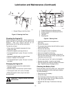
Adjusting the Forward and Reverse
Clutches
The forward and reverse clutches must be checked
every 100 hours. If the lining has worn to a thickness
of less than 0.150 inch (3.8mm), replace the lining.
The forward clutch is on the right side of the
transmission and the reverse clutch is on the left side
of the transmission (Figure 5).
NOTE: Damage will occur if the tractor is operated
with a lining thickness of less than 0.150 inch
(3.8mm).
Inspect and adjust the clutches as follows:
• Stop the engine and place the direction control
pedal in the “Neutral” position.
• Raise the rear fender.
• Measure the clearance in the slot. The correct
clearance is .030 inch (.76mm) to .060 inch
(1.5mm) for the forward clutch and .010 inch
(.25mm) to .030 inch (.76mm) for the reverse
clutch.
• Adjust the bolts which go through the flange on the
axle bearing retainer so that the forward-reverse
clutch springs are straight up and down when the
clutches have zero clearance. Lock the bolt in
place with the jam nut. Loosen the jam nut which
holds the slide rod bushing in place. Adjust the
bushing on the slide rod until the clearance is
correct. Lock the bushing in place with the jam nut.
• Lubricate the clutch once each season. Remove
the clutch and apply a film of high quality lithium
base grease to the splined clutch shaft. While the
clutch is off, check the lining wear. If the lining has
worn near the rivet heads, replace the lining.
Readjust the clutch as described above.
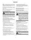
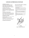
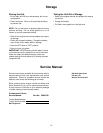
Adjusting the PTO Clutch
The PTO clutch should be adjusted whenever there is
less than .5 inches of free travel in the clutch lever
when it is in the “On” position. See Figure 6 to see
where this free travel is measured. The free travel
should be between .5 inch and 1.0 inch.
• Stop the engine and lock the brake.
• Loosen the bolts holding the switch bracket and
push the bracket down.
• Raise the rear fender.
• Push the PTO lever to “On”.
• Disconnect the PTO control from the transmission
lever.
12
Adjustments
CLEARANCE
MEASURE FREE TRAVEL HERE
Figure 6: PTO Clutch Adjustment