


Specifications
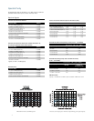
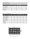
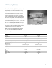
Model/Option No. Frequency Coverage Output Type
MG3691A 2 to 8.4 GHz K(f)
MG3692A 2 to 20 GHz K(f)
MG3693A 2 to 30 GHz K(f)
MG3694A 2 to 40 GHz K(f)
MG3695A 2 to 50 GHz V(f)
MG3696A 2 to 65 GHz V(f)
Option 4 10 MHz to 2.2 GHz Model No. Dependent
Option 5 10 MHz to 2 GHz Model No. Dependent
Option 22 0.1 Hz to 10 MHz Model No. Dependent
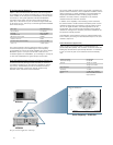
Options 4 and 5: Frequency extension down to 10 MHz
Two options are available to extend the 2 GHz low end frequency
limit of the base models down to 10 MHz. Option 4 uses a digital
down-converter (DDC) with successive divide-by-two circuitry.
It offers the best phase noise performance of the two choices, at
the expense of some analog performance <500 MHz. In that range,
analog sweep mode is not available, and pulse modulation
performance is specified as typical. In addition, frequency and
phase modulation mod index is scaled by the division ratio of each
band of the DDC. Option 5 maintains all analog performance by
using a heterodyne mixing down-converter.
Option 22: Frequency extension down to DC
If frequency coverage down to 0.1 Hz is desired, Option 22 can be
added with either Option 4 or 5. Option 22 uses Direct Digital
Synthesis (DDS) for CW and Step Sweep modes of operation.
Modulation and analog sweep are not available in the DDS band.
Frequency resolution <10 MHz is 0.02 Hz. Output power across the
complete instrument frequency range is degraded by 2 dB.
CW Mode
Output: Twenty independent, presettable CW frequencies
(F0 – F9 and M0 –M9).
Accuracy: Same as internal or external 10 MHz time base.
Internal Time Base Stability:
With Aging: <2 x 10
–9
/day (<5 x 10
–10
/day with Option 16)
With Temperature: <2 x 10
–8
/deg C over 0˚C to 55˚C
(<2 x 10
–10
/deg C with Option 16)
Resolution: 0.01 Hz
External 10 MHz Reference Input: Accepts external 10 MHz ±50 Hz
(typical), 0 to +20 dBm time base signal. Automatically disconnects
the internal high-stability time-base option, if installed. BNC, rear
panel, 50Ω impedance.
10 MHz Reference Output: 1 Vp-p into 50Ω, AC coupled.
Rear panel BNC; 50
Ω impedance.
Switching Time (typical maximum): <40 ms to be within 1 kHz of
final frequency.
Phase Offset: Adjustable in 0.1 degree steps.
Electronic Frequency Control (EFC) Input: –5V to +5V input range;
5 x 10
–7
.Fout Hz/V sensitivity (typical); ≤250 Hz Modulation BW;
Rear panel BNC; High Impedance
Phase-Locked Step Sweep Mode
Sweep Width: Independently selected, 0.01 Hz to full range. Every
frequency step in sweep range is phase-locked.
Accuracy: Same as internal or external 10 MHz time base.
Resolution (Minimum Step Size): 0.01 Hz
Linear/Log Sweep: User-selectable linear or log sweep.
In log sweep, step size logarithmically increases with frequency.
Steps: User-selectable number of steps or the step size.
Number of Steps: Variable from 1 to 10,000
Step Size: 0.01 Hz to the full frequency range of the instrument.
(If the step size does not divide into the selected frequency range,
the last step is truncated.)
Dwell Time Per Step: Variable from 1 ms to 99 seconds
Fixed Rate Sweep: Allows the user to set the total time of the
sweep, including lock time. Variable from 20 ms to 99 seconds.
Switching Time (typical maximum): <15 ms + 1 ms/GHz step size
or <40 ms, whichever is less, to be within 1 kHz of final frequency.
Analog Sweep Mode (Option 6)
Sweep Width: Independently selected from 1 MHz to full frequency
range. With Option 4, Digital Down Converter, Analog sweep is only
available ≥500 MHz. Analog sweep is not available <10 MHz with
Option 22.
Accuracy: The lesser of ± 30 MHz or (± 2 MHz + 0.25% of sweep
width) for Sweep Speeds of ≤50 MHz/ms. (typical)
Sweep Time Range: 30 ms to 99 seconds
Alternate Sweep Mode
Sweeps alternately in step sweep between any two sweep ranges.
Each sweep range may be associated with a power level.
Manual Sweep Mode
Provides stepped, phase-locked adjustment of frequency between
sweep limits. User-selectable number of steps or step size.
List Sweep Mode
Under GPIB control or via the front panel, up to 4 tables with 2000
non-sequential frequency/power sets can be stored and then
addressed as a phase-locked step sweep. One table of 2000
points is stored in non-volatile memory, all other tables are stored in
volatile memory.
Switching Time (typical maximum): <25 ms to be within 1 kHz of
final frequency.
Programmable Frequency Agility
Under GPIB control, up to 3202 non-sequential frequency/power
sets can be stored and then addressed as a phase-locked step
sweep. Data stored in volatile memory.
Switching Time (typical maximum): <25 ms to be within 1 kHz of
final frequency.
Markers
Up to 20 independent, settable markers (F0 – F9 and M0 – M9).
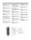
Video Markers: +5V or –5V marker output, selectable from system
menus. AUX I/O connector, rear panel.
Intensity Markers: Produces an intensity dot on analog display
traces, obtained by a momentary dwell in RF sweep, in analog
sweeps of <1s.
Marker Accuracy: Same as sweep frequency accuracy.
Marker Resolution:
Analog Sweep: 1 MHz or Sweep Width/4096 which ever is greater.
Step Sweep: 0.01Hz.
Frequency Coverage:
2