


10
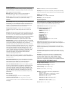
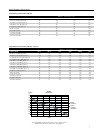
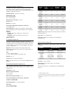
TRACE A: Ch1 8PSK Meas Time
1.5
-1.5
-1.9607643757 1.96078437567
I - Q
300
M
/div
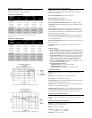
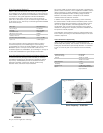
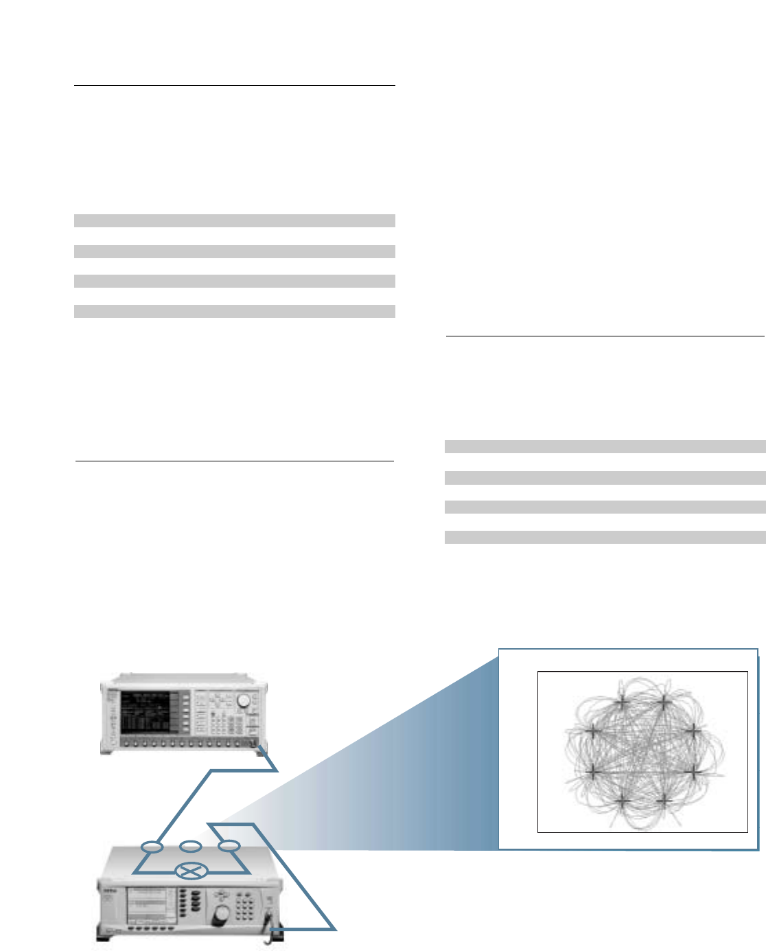
MG3681A
MG3690A
Carrier Frequency = 38.000 GHz
IF RF
User-Defined Modulation Waveform Software (Option 10)
An external software package provides the ability to download
user-defined waveforms into the internal LF Generator’s (Option
23) memory. The MG3690A provides as standard with the LF
Generator sinusoidal, square-wave, triangle, positive ramp,
Gaussian noise, and uniform noise waveforms.
IF Up-Conversion Application and Setup
IF Up-Conversion (Option 7)
Option 7 adds an internal mixer that can be used for the generic
up-conversion of an IF signal. The mixer’s RF, LO, and IF ports are
made available at the rear panel of the MG3690A, via three female
K-Connectors. The typical application will feed the MG3690A
microwave output, which can be moved to the rear panel via
option 9K, to the mixer’s LO port. An external IF signal will be fed
to the mixer’s IF port. The new up-converted signal will be available
at the mixer’s RF port.
Mixer Type Double Balanced
RF, LO Range 1 to 40 GHz
IF Range DC to 700 MHz
Conversion Loss 10 dB Typical
Max Power into any Port 30 dBm
Isolation, RF to LO 23 dB
LO Drive Level (recommended) +10 to +13 dBm
Input P
1dB
+3 dBm Typical
The IF Up-Conversion option is particularly useful to create a
microwave frequency IQ-modulated signal. Lower frequency
IQ-modulated RF sources are readily available, such as the Anritsu
MG3681A. Option 7’s IF input can be used to feed in an IQ-
modulated signal from an MG3681A, up-converting it to as high as
40 GHz with an MG3694A. A typical setup is shown below.
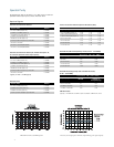
Frequency Range 2 to 18 GHz
Attenuation Range 0 to 60 dB
Flatness ±2 dB, 0 to 40 dB
±2 dB, 40 to 60 dB
Step Response < 1 ms
Sensitivity -10 dB/V
Insertion Loss < 6 dB (when engaged)
Input Rear Panel BNC connector
High Impedance
Scan Modulation (Option 20)
Option 20 adds a microwave linearly controlled alternator to
provide deep AM capability. This modulator is inserted outside the
leveling loop but before the optional step alternator. It is switched
in and out of the RF path. Scan modulation is driven externally
only.
Two look-up tables of 65,536 points can be used to generate two
pseudo-random waveforms, one for amplitude modulation and the
other for frequency or phase modulation. The download files are
simple space-delimited text files containing integer numbers
between 0 and 4095, where 0 corresponds to the minimum
modulation level and 4095 the maximum.
In addition to the capability of downloading custom waveforms,
the software offers a virtual instrument modulation panel. Custom
modulation setups with user waveforms can be stored for future
use. For IFF signal simulation, the internal generators can be
synchronized. They can also be disconnected from the internal
modulators, making the low frequency waveforms available at the
rear panel for external purposes.
One application of this feature is storing an antenna pattern wave
form in memory and using it to feed the external input to the scan
modulator, Option 20.