


ASSEMBLY
GR60/72 02/07 Assembly Section 3-2
© 2007 Alamo Group Inc.
ASSEMBLY
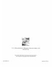
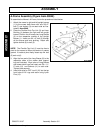
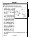
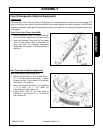
A-Frame Assembly (Figure Asm-00049)
To assemble the Mower’s A-Frame, follow the procedures listed below:
1. Attach the mower’s right and left upright braces
(1) to the mower deck frame with one 5/8x 2”
bolt (7) and locknut (9) one each side as illus-
trated in Asm-0049.
2. Place the Flexible Hitch Top Link (3) and inner
Bushing (4) between the right and left upright
braces. Position the A-frames two Long Braces
(2) on the respective outside of the Upright
Braces (1). Insert one 3/4 x 6” bolt (5) through
all four braces and inner bushing. Attach and
tighten locknut (6) to bolt (5).
NOTE: The Flexible Top Link (3) must be free to
pivot for the mower to follow the contour of uneven
ground. If unable to pivot freely, loosen top link bolt
(5) and nut (6).
3. Align the free end of the Long Braces (2) to the
respective sides of the mower deck support
lugs as illustrated. Align holes of Long Braces
and mower deck Lugs and insert one 5/8 x 1-1/
2” bolts (10) and locknuts (11) to each side.
Tighten bolts securely.
4. Insert hitch pins for CAT I and II (12) into the top
front holes of lift Lugs and retain using Lynch
Pins (13).