ASSEMBLY
A96B 03/06 Assembly Section 3-6
© 2006 Alamo Group Inc.
ASSEMBLY
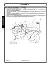
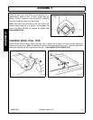
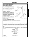
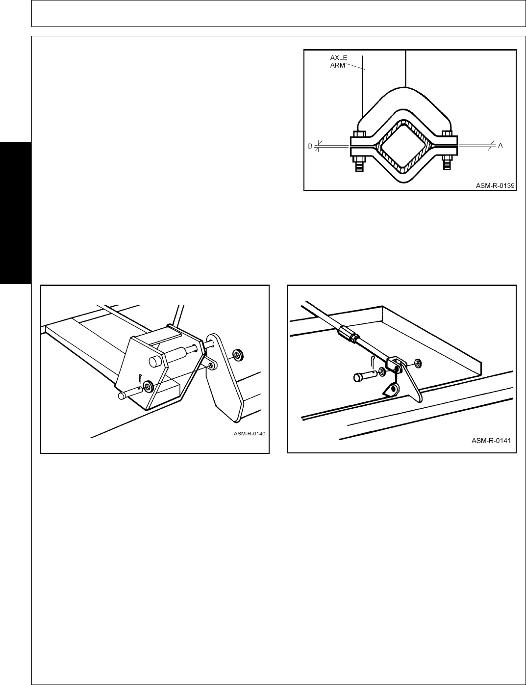
Attach the Axle Arms to the Main Axle maintaining Dim. A
approximately equal to Dim. B when clamp bolts are
tighten. However, these Dim. may vary slightly if needed to
help level the Mower Deck from side to side.
Note: Axle arms may be moved on the main tube to the
desired wheel tread but it is always recommended that
wheels be placed as wide as possible for stability. See
Figure ASM-R-0139.
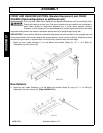
CONTROL RODS - PULL TYPE
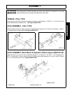
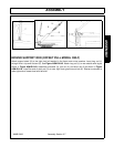
Attach the two level-lift control rods to the lower lugs on tongue and to lugs on the rear axle tube using pins,
washers and cotter pins. Note: The adjusting nuts on control rods should be to rear of machine and should
always be adjusted with equal tension on both rods. Figure ASM-R-0140 & ASM-R-0141.


