


ASSEMBLY
UGR 04/06 Assembly Section 3-3
© 2006 Alamo Group Inc.
ASSEMBLY
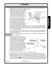
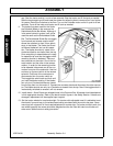
5. Attach the curb lift cylinder to the carriage and subframe lug with the clevis pins and cotterpins.
NOTE: Cylinder rod end attaches to the subframe lug.
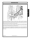
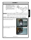
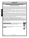
6. Complete the Assembly of the valve stand
by installing the valve and switch operation
decals to the switch mount of the valve
stand. Install the toggle switch (4) from the
inside of the switch mount on the valve
stand. Use the nut included with the switch
on the underside of the mount to adjust the
position of the switch so that there is
approximately 1/8” of thread protruding out
of the top. Attach using the Switch Boot (2).
Insert the Push/Pull switch (4) from the
inside of the switch mount on the valve
stand through the front face. Attach using
the included nut. Attach the Red Push/Pull
knob (3) to the stem of the Push/Pull Switch
(4). Attach the Harness to the Switches according to the instructions shown in Figure Asm-R-
0242. Attach the valve to the valve stand. Carefully route the harness to the Motor Control Valve
(7) on top of the tank. Attach the connector (6) to the two connectors on the Motor Control Valve
(7). See Figure Asm-R-0242
7. Connect the hydraulic circuit in accordance with the Hydraulic Kit Installation Instructions, tank to
pump, pump to valve and so on. Use a paste sealer on all pipe thread connections. NOTE: DO
NOT USE TEFLON TAPE!
Do not overtighten connections. Cracked parts and fittings due to overtightening will not be
covered under warranty.
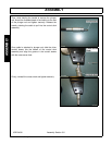
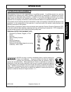
8. Connect the electric wire harness to the
switches and tractor. Disconnect the nega-
tive lead from the battery terminal. Remove
the ignition switch access panel and/or igni-
tion switch. Cut the “IGNITION-START”
wire approximately 3” from the ignition
switch. Strip off 1/4” insulation from the end
of each wire. Loop in the brown wires using
the attached butt connectors. Remove 1/4”
of insulation form the “IGNITION ACCES-
SORY” switch and tee in red wire. Insulate
connection with electrical tape. (Alternately,
Tee-Splices may be utilized) Attach the
black ground wire to a panel screw or other
ground point. (See Figure Asm-R-)
9. Lubricate all points by referring to the figure in the Maintenance Section.
10. After making sure all of the hydraulic connections have been made and are tight, fill the reservoir
with a good grade of clean Universal Tractor Hydraulic Oil (P/N 02966303 - 5 Gal Container).
NOTE: Always add oil to the reservoir using a system that filters the oil prior to being added to the
tank. Never Assume that any
oil, even new oil in a new container is contaminant free! To rapidly fill
the tank, remove the screw cap from the top of the filter housing and remove the filter cartridge
from the bowl. Fill the tank until the oil is at the top of the sight gauge. Re-install the filter and screw