


GB
GB 2
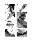
b) Bowden cables for the wheel drive
This mower has a forward drive and a
reverse drive.
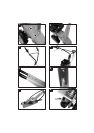
1.) Bowden cable for reverse drive
21 The Bowden cable for the reverse drive
comes out of the housing below the engine
on the
right (viewed in the direction of
travel) and is additionally labelled R..
22 Insert the bent hook of the .R. Bowden
cable into the lower hole on the inward side
of the right-hand handlebar lever.
23 y Unscrew the foremost nut on the adjuster "a".
y Insert the adjuster in the holder and
retighten the nut.
24 Lay the Bowden cable along the inner side
of the handlebar console.
Correct adjustment of the Bowden cable:
see under: "Adjustment of Bowden
cables" in the operating manual of the
mower.
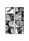
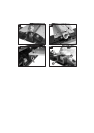
2.) Bowden cable for forward drive
25 The Bowden cable for the forward drive is
on the right side of the housing viewed in
the direction of travel.
26. y Insert the bent hook of the Bowden cable
into the lower hole on the outward side of
the left-hand handlebar lever.
y Insert the Bowden cable sleeve "a" into
the holder on the handlebars.
27 Adjust the lower end of Bowden cable on
the housing to the correct setting.
See under: "Adjustment of Bowden cables"
in the operating manual of the mower.
c) Bowden cable for cutter bar
The Bowden cable for the cutter bar is on the
left side of the housing viewed in the direction
of travel.
i
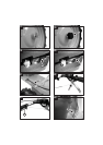
28 Screw back both nuts on the upper Bowden
cable adjuster all the way.
29 Thread the Bowden cable through the
console.
30 Thread the Bowden cable through guide on
the console.
31 Thread the bent hook through the hole in
the holder and push the adjuster up to the
holder.
There is
no insertion slit on the holder!
32 y Insert the bent hook through the red
handlebar lever.
y Set the lower adjuster on the housing to
its middle position.
i
Correct adjustment of the Bowden cable:
See under: "Adjustment of Bowden
cables" in the operating manual of the
mower.
i
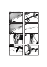
33 Bind the Bowden cables together with a
cable tie on the inner side of the console.
Protective cover
34 Remove the nuts and washers on the blade
holder.
35 Mount the protective cover and tighten the
nuts.
Do not completely tighten the upper nut
(width across flats 19 mm).
36 Mount the protective cap on the rear of the
housing and secure with a hexagonal
drilling screw Ø 4.8 x 16 (1x) and
washer Ø 5 (1x).