


19
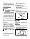
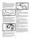
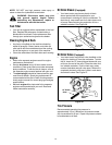
• Remove the blade from the spindle.
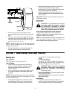
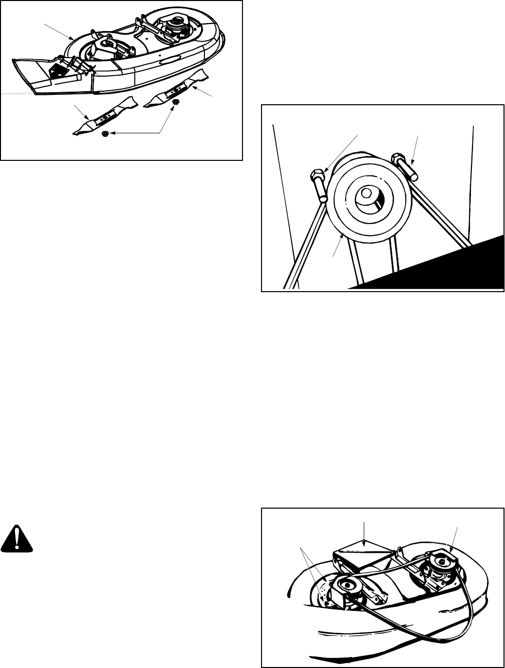
Figure 21
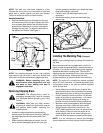
Sharpening Blade
• Remove the cutting blades by following the
directions in the preceding section.
• When sharpening the blades, follow the original
angle of grind as a guide. It is extremely important
that each cutting edge receives an equal amount of
grinding to prevent an unbalanced blade. An
unbalanced blade will cause excessive vibration
when rotating at high speeds, may damage the
tractor and/or could break, causing personal injury.
Balancing Blade
• The blade can be tested for balance by balancing it
on a round shaft screwdriver. Remove metal from
the heavy side until it balances evenly.
Reassembly
• When replacing blades, be sure to install the blade
with the side of the blade marked ‘‘Bottom’’ (or with
part number) facing the ground when the tractor is
in the operating position. Carefully align “star” on
blade with “star” on spindle. Secure with flange nut.
Blade Mounting Torque
Hex Flange Nut: 840 in. lb. min., 1080 in. lb. max.
• All nuts and bolts must be checked periodically for
correct tightness.
Belt Replacement
WARNING: Disconnect the spark plug
wire(s) and ground it against the engine.
Block the wheels of the unit.
NOTE: Figure 22 and Figure 25 are shown with the unit
tipped up for clarity. It is not necessary to tip the unit to
remove the belts. However, for convenience, if you
decide to tip it, remove the battery from the unit first.
• To prevent gasoline leakage, drain the gasoline, or
remove the fuel tank cap. Place a thin piece of
plastic over the neck of the fuel tank and screw on
the cap. Be certain to remove the plastic when
finished changing the belts. Block unit securely.
Deck Belt (38" and 42" Decks)
• Place the lift lever in the engaged (all the way
forward) position.
• Disconnect the spring which is attached to a
bracket on the transaxle, inside the right rear wheel.
Use a spring puller or other suitable tool.
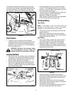
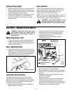
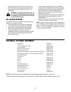
NOTE: When reassembling, make certain belt keeper
pins are assembled in the same locations from which
they were removed. See Figure 22.
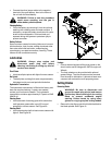
Figure 22
• Place the lift lever in the BLADES STOP position.
• Remove the belt keeper pins from the lower frame.
• Unhook the deck belt from the engine pulley.
• Place the lift lever in the engaged (all the way
forward) position.
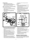
• Disconnect the stabilizer plate from the stabilizer
shaft assembly by removing the hairpin clips and
flat washers and sliding out the rod.
• Disconnect the six deck links by removing the
hairpin clips and flat washers.
• Place the lift lever in the BLADES STOP position.
• Slide the deck from beneath the lawn tractor.
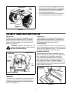
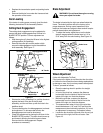
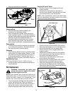
• Remove the belt guards at each deck pulley by
removing the self-tapping screws. See Figure 23.
• Remove and replace the belt, reassemble following
the instructions in reverse order.
Figure 23
Blade
Hex Flange
Nut
Deck
Blade
Belt Keeper Pins
Engine
Pulley
Self-Tapping
Screws
Stabilizer Plate
Belt Guard