


15
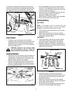
Setting Cutting Height
• Select the position for the lift lever which gives the
desired cutting height. Move the deck lift indicator
(if so equipped) so that the lift lever can be returned
to the same position after it is raised.
• Move the deck wheels (if so equipped) to the hole
location so the wheels are 1/4 inch above the
ground. All wheels must be placed in the same
relative position.
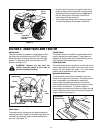
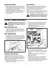
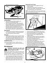
Grass Collector
Grass Collector Model OEM-190-063 is available as
optional equipment for lawn tractors with 38" and 42"
decks. Grass Collector Model OEM-190-103 is
available for lawn tractors with 46" decks.
NOTE: Under normal usage bag material is subject to
wear and should be checked periodically. Be sure to
use only factory authorized replacement bag.
WARNING: The mower should not be
operated without the entire grass catcher
or chute deflector firmly installed in place.
SECTION 6: MAKING ADJUSTMENTS
WARNING: Disconnect spark plug wires
and ground against the engine before
performing any adjustments, repairs or
maintenance.
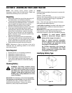
Manual Adjustment Seat
• To adjust the position of the seat, loosen the four
screws on the bottom of the seat. Slide the seat
forward or backward as desired. Retighten the four
screws. Refer to Figure 3.
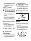
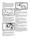
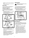
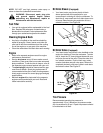
Quick Adjustment Seat
• To adjust the position of the seat, move the seat
adjustment lever (located under the seat) to the left
and slide the seat forward or backwards. Make sure
seat is locked into one of the six positions before
operating the lawn tractor. See Figure 15.
Figure 15
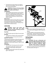
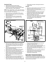
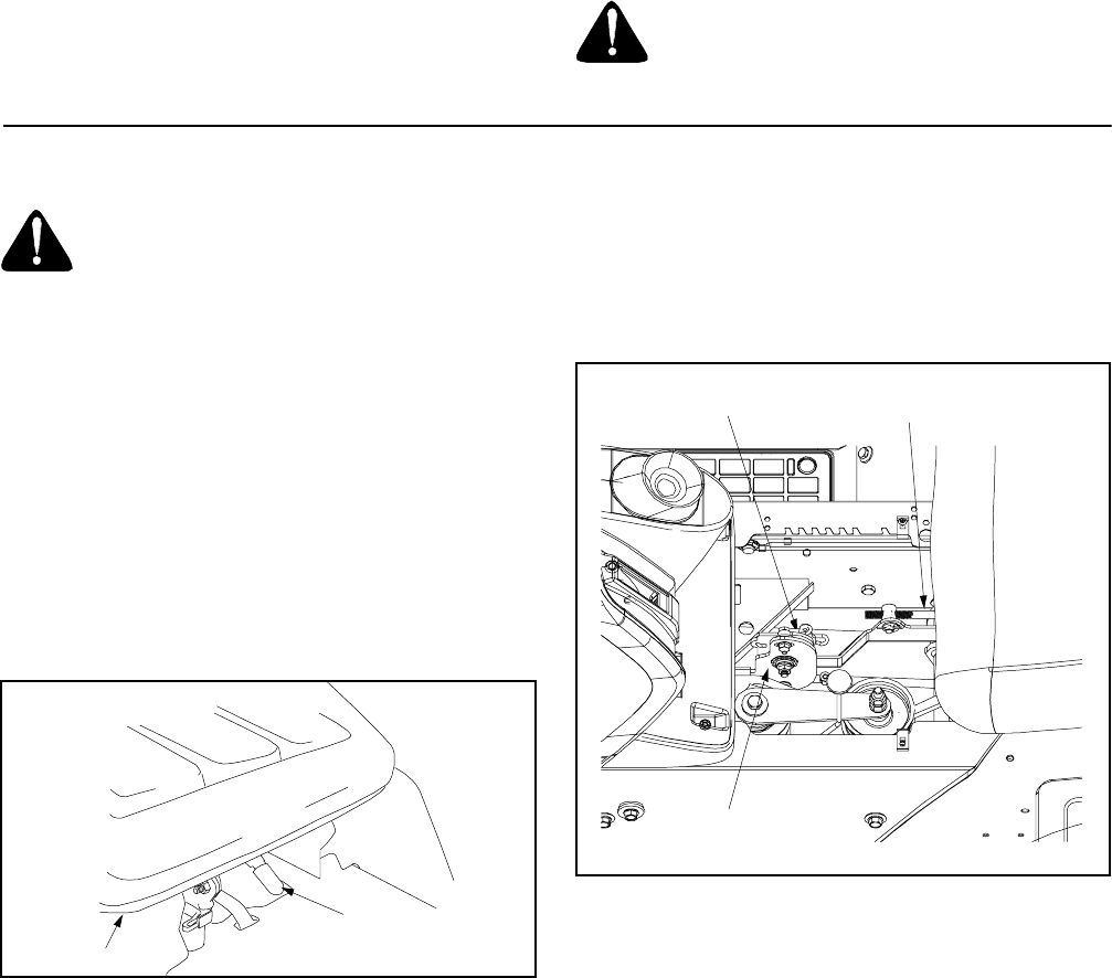
Hydrostatic Neutral Control
The hydrostatic transmission control is in correct
adjustment when the tractor does not move with the
engine running, the clutch engaged and the hydrostatic
control lever in the neutral position. If adjustment is
necessary, follow these steps:
• Raise both rear wheels off the ground by placing
blocks under the rear frame.
• Remove the transmission panel by removing the
parking brake knob and truss machine screws.
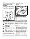
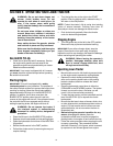
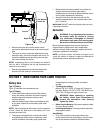
• Loosen the hex jam nut on the speed selector
adjusting rod. See Figure 16.
• Loosen the hex nut on the scissor mounting
bracket. See Figure 16.
Figure 16
• Start the engine and run at full throttle.
• Move hydrostatic control lever until you find neutral.
At this position, rear wheels will not rotate in either
direction.
• Depress the clutch-brake pedal until the scissor
brackets come together.
• Shut off the engine.
• Tighten hex nut on the scissor mounting bracket.
• Thread the speed selector rod in or out of the
ferrule until the hydrostatic control lever lines up in
neutral position on the speed control index bracket.
• Tighten hex jam nut against the ferrule.
Seat
Seat
Adjustment Lever
Speed Selector
Adjusting Rod
Scissor
Bracket
Scissor Mounting
Bracket