


16
• Replace the transmission panel and parking brake
knob.
• Remove the blocks from under the frame and test
the operation of the tractor.
Deck Leveling
If the tractor is cutting grass unevenly, level the deck
following instructions in the Assembly Section.
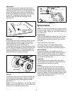
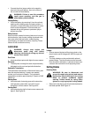
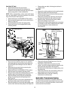
Cutting Deck Engagement
The cutting deck engagement may be adjusted to
ensure that deck is disengaged when lift lever is in
BLADES STOP position. Correct adjustment as
follows.
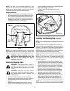
• With the engine off, place the lift lever in the highest
cutting position (first position).
• Remove the cotter pin and flat washer which
secure the disengagement rod to the stabilizer
shaft assembly. See Figure 17.
Figure 17
• Shorten the rod by threading it in, until the ferrule is
against the back of the slot in the lift shaft
assembly, and the rod lines up with the hole in the
stabilizer shaft.
• For more belt tension, the disengagement rod must
be lengthened. To decrease belt tension the
disengagement rod must be shortened.
• Check the adjustment by placing the lift lever in the
BLADES STOP position. The deck should move up
and forward, allowing the belt to become loose.
Start and test for disengagement. Repeat
procedure as necessary.
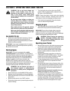
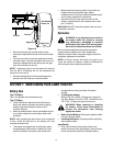
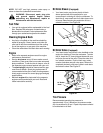
Brake Adjustment
WARNING: Do not have the engine running
when you adjust the brake.
The brake is located by the right rear wheel inside the
frame. The brake has been set at the factory to the
proper clearance. During normal operation of this
machine, the brakes are subject to wear and will require
periodic examination and adjustment.
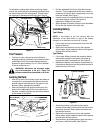
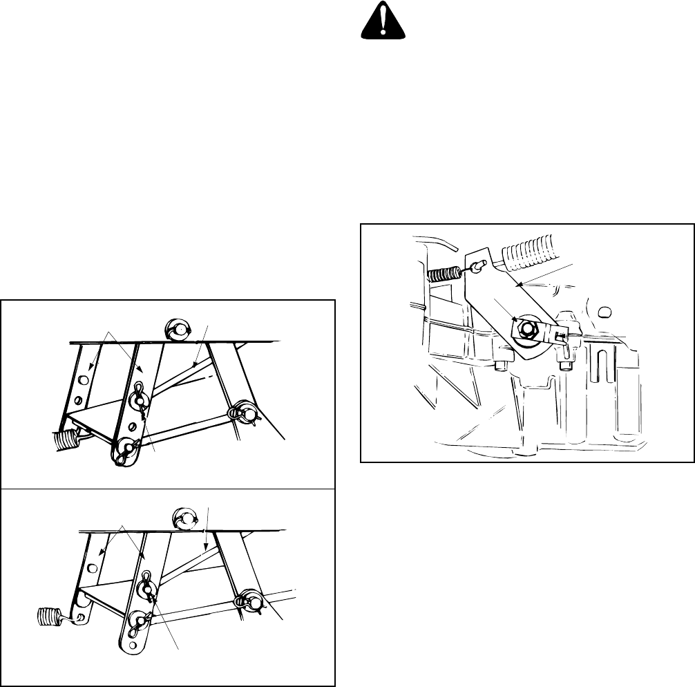
• To adjust the brake, adjust the nut so the brake
starts to engage when the brake lever is 1/4" to
5/16" away from the axle housing. See Figure 18.
Figure 18
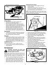
Wheel Adjustment
(Units with Adjustable Tie Rod)
If the tractor turns tighter in one direction than the other,
or if either the tie rod and ferrule are being replaced due
to damage or wear, the tie rod may need to be adjusted.
To do so, proceed as follows:
• Place the steering wheel in position for straight
ahead travel.
• In front of the pivot bar, measure the distance
horizontally from the inside of the left rim to the
inside of the right rim. Note the distance.
• Behind the pivot bar, measure the distance
horizontally from the inside of the left rim to the
inside of the right rim. Note the distance.
• The measurement taken in front of the pivot bar
should be between 1/16” and 5/16” less than the
measurement taken behind the pivot bar. If it is not,
an adjustment is necessary. Proceed as follows.
• Locate the ferrule at the right end of the tie rod, just
to the rear of the right, front tire of tractor. See
Figure 19.
38" Decks
Disengagement Rod
Disengagement Rod
Stabilizer Shaft
Assembly
Flat Washer &
Hairpin Clip
Stabilizer Shaft
Assembly
Flat Washer &
Hairpin Clip
42” or 46”
Decks
Nut
Brake Lever