


11
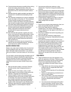
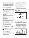
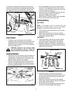
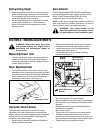
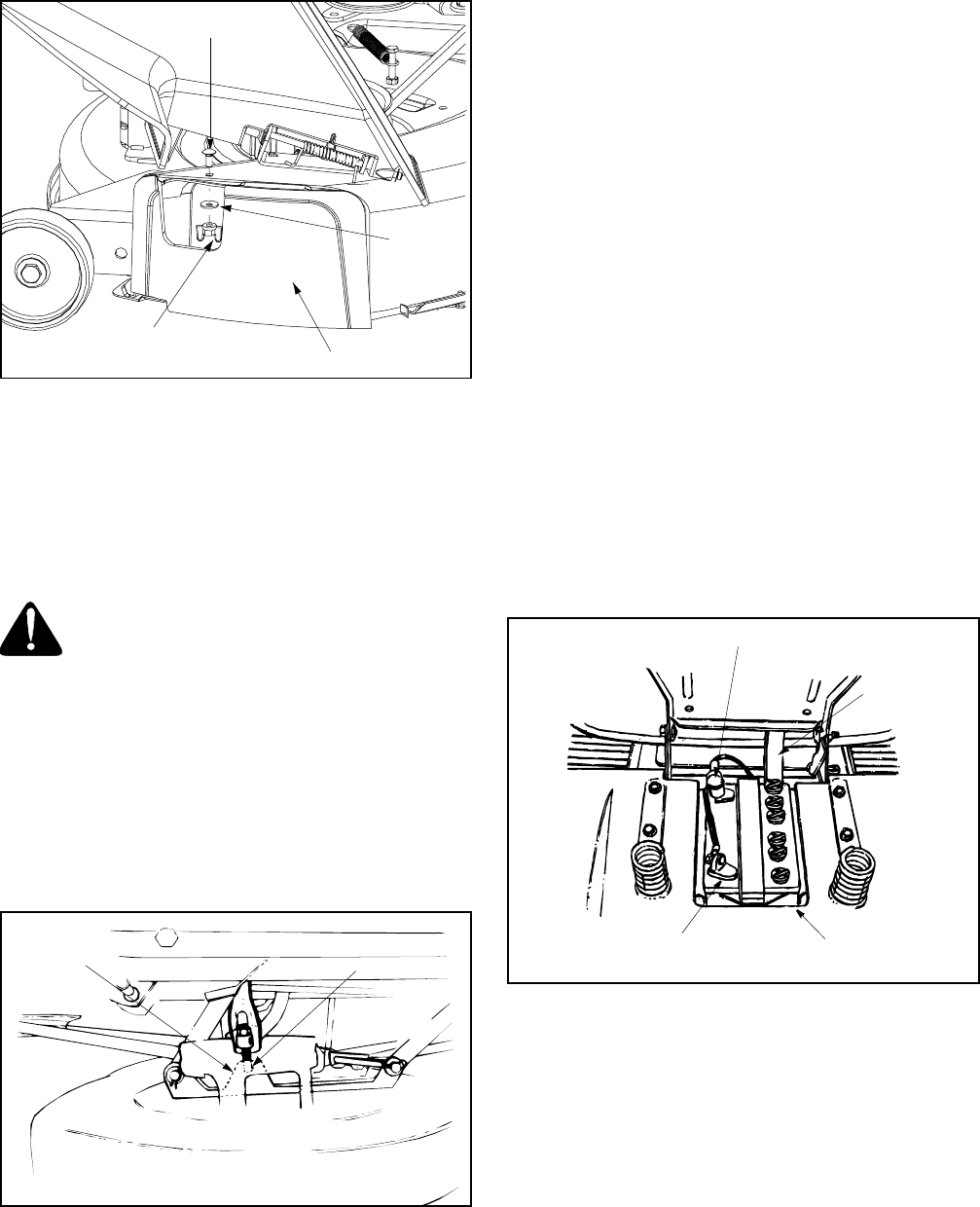
To operate the cutting deck without mulching, simply
remove the mulch plug by unthreading the plastic wing
nut which fastens it to the cutting deck. This will allow
the clippings to discharge out the side. See Figure 6.
Figure 6
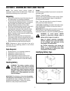
Tire Pressure
• The tires on your unit may be over-inflated for
shipping purposes. Reduce the tire pressure before
operating the unit. Recommended operating tire
pressure is approximately 10 p.s.i. Check sidewall
of tire for maximum p.s.i.
WARNING: Maximum tire pressure under
any circumstances is 30 p.s.i. Equal tire
pressure should be maintained on all tires.
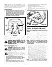
Leveling the Deck
• With unit on hard, level surface, place the blades in
a straight line, and measure the distance from the
outside edge of the blade tips to the ground. If the
distance varies, adjustment is needed.
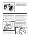
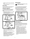
• Remove the hairpin clip and flat washer from the
bottom of the adjustable lift link on the left side of
the deck. Locate the hairpin clip and the flat washer
on the inside of the lift link.
Figure 7
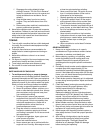
• Pull the adjustable lift link out of the deck hanger
channel. Turn the adjustable lift link up or down as
necessary to level the deck. Usually only one or two
turns are needed. See Figure 7.
• Insert the end of the adjustable lift link into the hole
in the deck hanger channel. Recheck the
adjustment. Readjust if necessary.
• When the deck is levelled, secure end of adjustable
lift link with flat washer and hairpin clip.
Installing Battery
Type A Battery
NOTE: If the battery is put into service after the
expiration of the date shown on top of the battery,
charge it for a minimum one hour at 6-10 amps.
• Lift the seat and remove the plastic cover from the
negative terminal.
• Remove the hex bolt and nut from the negative
(black) cable. Attach negative cable to the negative
terminal with this bolt and nut.
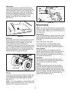
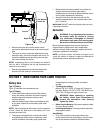
Type B Battery
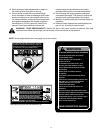
• Lift the seat. Make sure both the negative (black)
cable and the positive (red) cable are routed up
through the battery compartment. See Figure 8.
• Replace the battery in the battery compartment as
it was before. Make sure that the positive terminal is
toward the front of the unit.
Figure 8
• Attach the positive (red) cable to the positive
terminal of the battery. Secure with hex bolt and nut
previously removed. Slide rubber boot down over
the positive terminal.
• Remove the hex bolt and nut from the negative
(black) cable. Attach negative cable to the negative
terminal with this bolt and nut.
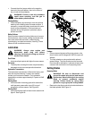
• Secure battery by hooking battery strap into slot in
rear frame, under the fender. See Figure 9.
Carriage Screw
Bell
Mulch Plug
Wing Nut
Washer
Deck Hanger
Channel
Adjustable
Lift Link
Positive Terminal
Battery
Strap
Negative
Terminal
Battery
Compartment