


6
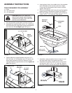
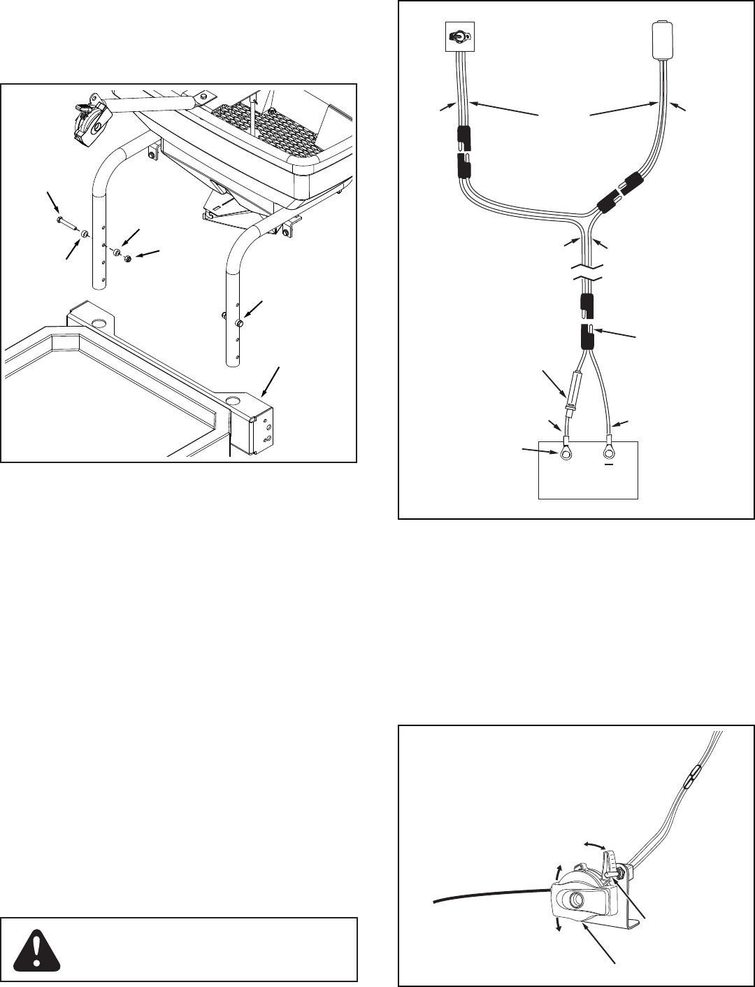
FIGURE 9
5/16 x 2"
HEX BOLT
SPACER
SPACER
5/16"
NYLOCK
NUT
ASSEMBLED
BOLT, SPACERS
AND NUT
MOUNTING
BRACKET
FIGURE 10
WIRING INSTRUCTIONS
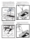
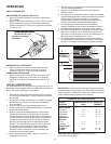
When properly connected, the spreader motor and impeller
will run clockwise viewed from above.
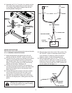
Movethespreader'sowcontrollevertotheoff17.
position so that the "ON-OFF" switch is turned off.
Connect the short (fused) wire harness to the vehicle 18.
battery by connecting the red wire to the positive
post and the brown wire to the negative post on the
battery. The wire harness may be left permanently
attachedtothebattery.Seegure10.
Connect the long wire harness to the spreader by 19.
connecting the red and white wires to the switch and
the brown and white wires to the spreader motor.
Refertogure10.
Connect the long wire harness to the short (fused) 20.
wire harness. Be sure the wires are clear of any
moving parts, hot engine parts, or pinch points.
Use nylon ties provided to safely secure the wiring 21.
away from hot engine parts, rotating parts and pinch
points.
NEVER allow negative pin on plug to come
in contact with positive "hot" post on battery.
Fire or explosion can result!
BROWN
RED
FUSE AND HOLDER
POSITIVE
"HOT" POST
NEGATIVE PIN
BROWN
RED
BATTERY
+
SWITCH
MOTOR
BROWN
RED
WHITE
FIGURE 11
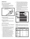
Movetheowcontrollevertothe"ON"position.Flip22.
the "ON-OFF" switch on and check that the motor
runs clockwise. If it does not, refer to the wiring
diagramingure10andrecheckthehookup.
Movetheowcontrolleverto"OFF".Thisshould23.
turn the "ON-OFF" switch off. If it does not, you can
loosenthecontrolandrotateitenoughthattheow
control lever, when moved to the "OFF" position will
turntheswitchoff.Seegure11.
"ON-OFF"
SWITCH
FLOW CONTROL
ON-OFF
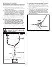
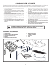
Assemble two 5/16 x 2" hex bolts, four spacers and two 16.
5/16" nylock nuts to either the top or next to top holes
in the hopper tubes. Slide the hopper tubes into the
mountingbracket.Seegure9.