


Performance Test and Calibration - B
81
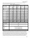
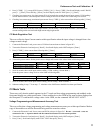
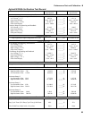
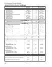
6. Set power source voltage and current values as listed in following table.
N3302A N3303A N3304A N3305A N3306A
Power Source Voltage Setting 50V 96V 20V 50V 20V
Power Source Current Setting 3.5A 1A 3A 3.5A 3.5A
7. Wait 3 seconds. Calculate and record resistance range 4 high resistance point
Transient Generator Mode Tests
This test verifies that the transient generator frequency and duty cycle circuits are within specification.
Frequency and Duty Cycle Accuracy
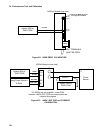
1. Connect Electronic Load, Power Source, Current Probe and Oscilloscope as shown in figure B-5.
2. Turn on the Electronic Load and press [ Recall ], scroll till display reads *RST and press [ Enter ].
3. On the Electronic Load front panel keypad:
a. Press [ Curr ] scroll until display reads C:TLEV. Press 10 then [ Enter ].
b. Press [ Tran ] scroll until display reads T:FREQ. Press 1000 then [ Enter ].
c. Press [ Tran ], press [ Input ] key until display reads TRAN ON then press [ Enter ].
4. Turn on power source and set for 10 volts and15 amperes.
5. Turn on and set oscilloscope:
a. Adjust Vertical for 1:1 probe.
b. Adjust Vertical for 20 mV/div.
c. Adjust horizontal for 500 uS/div
d. On measurement keypads Press shift key and select frequency and duty cycle for channel 1.
6. Connect current probe to channel 1 on oscilloscope, turn on current probe and set to 10mV/div.
7. Read measurements from oscilloscope screen and enter on test card. The oscilloscope may require 2 or 3 complete
waveforms to make measurements.