


Installation - 3
49
Application Connections
Local Sense Connections
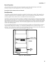
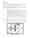
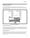
Figure 3-10 illustrates a typical setup with module number 1 connected for constant current or constant
resistance operation. Local sensing is used in applications where lead lengths are relatively short, or where load
regulation is not critical. The sense switch must be set to LCL. Load leads should be bundled or tie-wrapped
together to minimize inductance.
Figure 3-10. Local Sensing
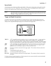
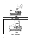
Remote Sense Connections
Figure 3-11 illustrates a typical setup with module number 1 connected for remote sense operation. The remote
sense terminals of module 1 are connected to the output of the power supply. Remote sensing compensates for
the voltage drop in applications that require long lead lengths. It is only useful when module 1 is operating in
CV or CR mode, or when using voltage readback. The sense switch must be set to RMT. Load leads should be
bundled or tie wrapped together to minimize inductance.
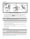
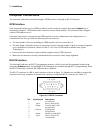
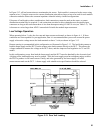
Parallel Connections
Figure 3-12 illustrates how modules can be paralleled for increased power dissipation. Up to six modules can be
directly paralleled in CC or in CR mode. Modules cannot be paralleled in CV mode. Each module will
dissipate the power it has been programmed for. For example, if two modules are connected in parallel, with
module number 1 programmed for 10 A and module number 2 programmed for 20A, the total current drawn
from the source is 30 A.
N3300A