


3 - Installation
48
Computer Connections
The electronic load can be controlled through a GPIB interface or through an RS-232 interface.
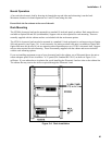
GPIB Interface
Each electronic load has its own GPIB bus address, which can be set using the front panel Address key as
described in Chapter 5. GPIB address data is stored in a non-volatile memory. The electronic load is shipped
with its GPIB address set to 5.
Electronic loads may be connected to the GPIB interface in series configuration, star configuration, or a
combination of the two, provided the following rules are observed:
♦ The total number of devices including the GPIB interface card is no more than 15.
♦ The total length of all cables used is no more than 2 meters times the number of devices connected together,
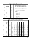
up to a maximum of 20 meters. (Refer to Table 2-2 for a list of GPIB cables available from Agilent
Technologies.)
♦ Do not stack more than three connector blocks together on any GPIB connector.
♦ Make sure all connectors are fully seated and the lock screws are firmly finger-tightened.
RS-232 Interface
The electronic loads have an RS-232 programming interface, which is activated by commands located in the
front panel Address menu. All applicable SCPI commands are available through RS-232 programming. When
the RS-232 interface is selected, the GPIB interface is disabled.
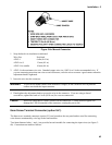
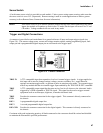
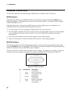
The RS-232 connector is a DB-9, male connector as shown in figure 3-9. Adapters are available to connect the
electronic load to any computer or terminal with a properly configured DB-25 connector (see Table 2-2).
1 2 3 4 5
6 7 8 9
Figure 3-9. RS-232 Connector
Pin Input/Output Description
1 - no connection
2 Input Receive Data (RxD)
3 Output Transmit Data (TxD)
4 - not applicable
5 Common Signal ground
6 - not applicable
7 Output Request to Send (RTS)
8 Input Clear to Send (CTS)
9 - No connection