MODEL 66-80 VIBRATORY DRIVER/EXTRACTOR
VII. GENERAL DATA
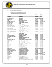
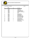
B. SCREWS AND BOLTS (CONTINUED)
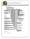
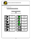
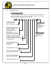
3. Some screws or bolts require a specific torque when replacing. For
identification of these bolts and a more thorough understanding of torque, refer
to page IV-10.
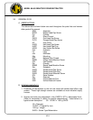
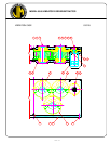
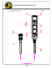
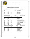
C. SERIAL NUMBER LOCATIONS
1. The following J&M vibratory units are serial numbered separately:
a. Vibrator
b. Power unit
c. Piling clamps
d. Caisson beams
e. 90 deg. clamp adapter
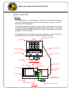
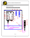
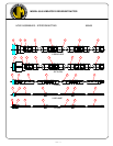
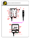
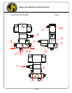
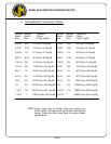
2. In addition to the serial number plate itself (on vibrators, power units and
clamps), the serial number is stamped into each unit in one or more places as
follows:
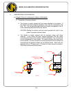
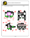
a. Vibrator stamped twice - once on top right side of suppressor housing,
once on bottom lip of vibration case on right side of motors' side.
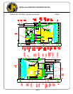
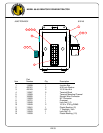
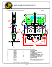
b. Power unit stamped twice - once on control panel side of unit at right
corner of reservoir, once on sub-base inside door below hex-key rack.
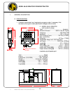
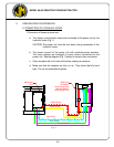
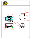
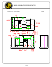
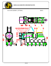
c. Model 196 universal clamp is stamped three times - once between the
cylinder and pile guide, once above the grease fitting, and once on the
flange of the cylinder housing.
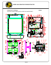
d. Model 122 caisson clamp stamped twice - once on side of the body at the
jaw opening nearest the fixed jaw side, and once on the underside of the
body under the pile guide on the cylinder side.
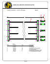
e. Caisson beam is stamped three times - once on top center, once in center
of both sides of flange.
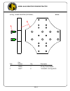
f. 90 deg. clamp plate stamped twice - once on top center, once on side.
VII-2