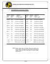
MODEL 66-80 VIBRATORY DRIVER/EXTRACTOR
II. PREPARATION FOR OPERATION
E. CONNECTION OF HYDRAULIC HOSES (CONTINUED)
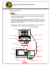
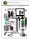
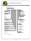
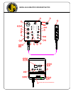
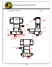
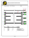
2. Connection of hoses at vibrator.
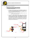
a. The vibrator is usually shipped with the hoses attached to the vibrator. If
the hoses have been shipped separately, they must be connected in the
field. Fig. 1 on the previous page shows the correct arrangement of the 5
hoses connecting the power unit to the vibrator.
CAUTION: Starting the vibrator with the hoses reversed will result in low
power or possible ruptured hoses.
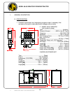
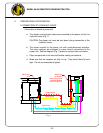
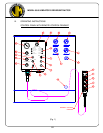
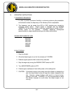
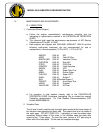
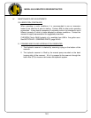
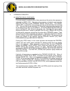
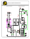
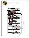
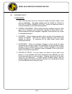
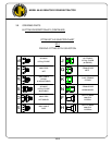
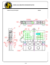
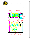
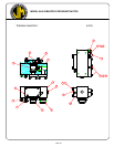
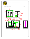
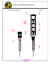
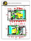
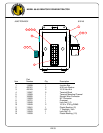
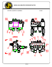
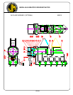
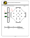
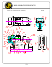
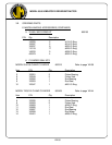
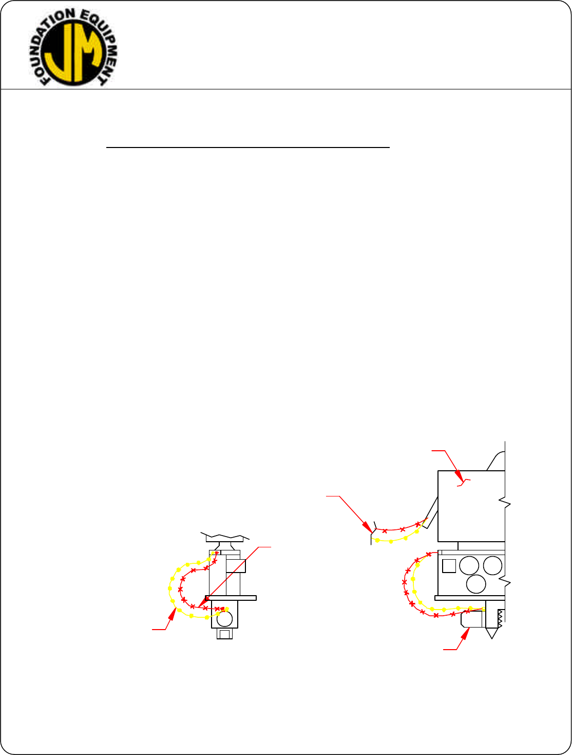
b. The vibrator is usually shipped with the hydraulic clamp and hoses
attached. If the clamp has been shipped separately, the two hoses
connecting the clamp to the vibrator must be connected. Fig. 2 shows the
correct arrangement of these hoses. For caisson clamps, four hoses must
be connected. The two connections on the opposite end of the vibrator are
reversed from the positions shown on the drawing below. Both ends are
stamped with an “O”(open) and a “C”(close) to insure correct connection.
The clamp connections are the same.
II-4
(Fig. 2)
Close Clamp
Open Clamp
Hose "O"
Hose "C"
66 Vibrator
196 Clamp
To 950 Power Unit
(See Fig. 1)