MODEL 66-80 VIBRATORY DRIVER/EXTRACTOR
III. OPERATING INSTRUCTIONS
A. COMPLETION OF SET-UP AND MAINTENANCE
1. Complete all preparation as described in Section II.
2. Read Section IV - MAINTENANCE AND ADJUSTMENTS and perform any
required maintenance.
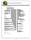
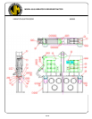
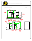
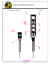
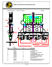
B. CONTROL PANEL
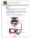
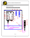
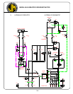
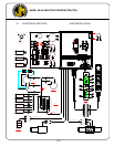
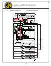
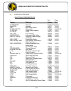
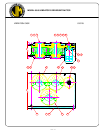
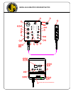
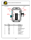
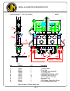
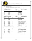
1. The control box (Fig. 1, page III-1) at the side of the power pack contains the
controls and gages for the diesel engine and the vibrator and the OPERATION
AND MAINTENANCE INSTRUCTIONS.
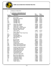
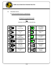
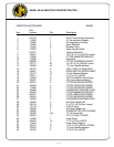
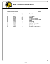
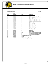
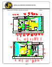
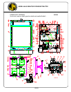
2. Control panel contains the following controls, gages and shutdown indicators.
a. Engine Tachometer
b. Engine Oil Pressure Switch Gage
c. Engine Water Temp Switch Gage
d. Engine Ammeter
e. Hydraulic Oil Temperature Switch Gage
f. Engine Hour Meter
g. Main Power Switch - ON-OFF Switch & Circuit Breaker
h. Engine - ON-OFF-START - Switch for Diesel Engine
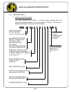
i. Engine Shutdown Reset Button - over ride button for engine shutdown
switch. Must be held in until oil pressure exceeds 30 PSI.
j. Vibrator Stop Button
k. Vibrator Start Button - with clamp light.
l. Clamp Switch - open - close.
m. Emergency Stop - pull out to stop engine.
n. Emergency Stop - push to stop engine.
o. Engine Throttle (Manual)
p. Pressure Gage - Forward
q. Engine Throttle (Remote Electric)
r. Pressure Gage - Close Clamp
s. Pressure Gage - Open Clamp
t. Shutdown indicator lights (6) See notes below.
u. Remote - Local Switch
v. Pressure Gage - Brake
Notes: 1. Engine Oil Pressure shutdown indicator - comes on if engine has been
shut down automatically due to engine oil pressure being low.
2. Engine Water Temperature shutdown - comes on if engine has been shut
down automatically due to engine water overheating.
III-2