59
Thermistors —
Electronic control uses 4 to 10 ther-
mistors to sense temperatures used to control the operation of
chiller.
Thermistors T1-T9 vary in their temperature vs resistance
and voltage drop performance. Thermistor T10 is a 10 kΩ in-
put channel and has a different set of temperature vs resistance
and voltage drop performance. Resistances at various tempera-
tures are listed in Tables 32A-33B.
LOCATION — General locations of thermistor sensors are
shown in Fig. 7-10. See Table 2 for pin connection points.
REPLACING THERMISTOR T2
1. Remove and discard original sensor and coupling. Do
not disassemble new coupling. Install assembly as
received. See Fig. 32.
2. Apply pipe sealant to
1
/
4
-in. NPT threads on replacement
coupling, and install in place of original. Do not use the
packing nut to tighten coupling. Damage to ferrules will
result.
3. Thermistor T2 (entering fluid temperature) should not be
touching an internal refrigerant tube, but should be close
enough to sense a freeze condition. Recommended dis-
tance is
1
/
8
in. (3.2 mm) from cooler tube. Tighten pack-
ing nut finger tight to position ferrules, then tighten 1
1
/
4
turns more using a back-up wrench. Ferrules are now at-
tached to the sensor, which can be withdrawn from cou-
pling for service.
REPLACING THERMISTORS T1, T5, T6, T7, AND
T8 — Add a small amount of thermal conductive grease to
thermistor well. Thermistors are friction-fit thermistors, which
must be slipped into wells located in the cooler leaving fluid
nozzle for T1, in the cooler head for T5 and T6 (EXV units
only), and in the compressor pump end for T7 and T8 (EXV
units only).
THERMISTORS T3 AND T4 — These thermistors are
located on header end of condenser coil. They are clamped on
a return bend.
THERMISTOR/TEMPERATURE SENSOR CHECK — A
high quality digital volt-ohmmeter is required to perform this
check.
1. Connect the digital voltmeter across the appropriate
thermistor terminals at the J8 terminal strip on the
Main Base Board for thermistors T1-T6, T9, T10; or
the J5 terminal strip on the EXV Board for thermistors
T7 and T8 (see Fig. 33). Using the voltage reading
obtained, read the sensor temperature from
Tables 32A-33B. To check thermistor accuracy, mea-
sure temperature at probe location with an accurate
thermocouple-type temperature measuring instru-
ment. Insulate thermocouple to avoid ambient temper-
atures from influencing reading. Temperature
measured by thermocouple and temperature deter-
mined from thermistor voltage reading should be
close, ± 5° F (3° C) if care was taken in applying ther-
mocouple and taking readings.
2. If a more accurate check is required, unit must be shut
down and thermistor removed and checked at a known
temperature (freezing point or boiling point of water) us-
ing either voltage drop measured across thermistor at the
J8 or J5 terminals, by determining the resistance with
chiller shut down and thermistor disconnected from J8 or
J5. Compare the values determined with the value read by
the control in the Temperatures mode using the Marquee
display.
Sensor T2 is installed directly in the fluid circuit. Relieve
all pressure or drain fluid before removing.
FLUID-SIDE TEMPERATURE SENSOR (T1) AND
REFRIGERANT TEMPERATURE SENSOR (T5, T6, T7, T8)
FLUID-SIDE TEMPERATURE SENSOR (T2)
NOTE: Dimensions in ( ) are in millimeters.
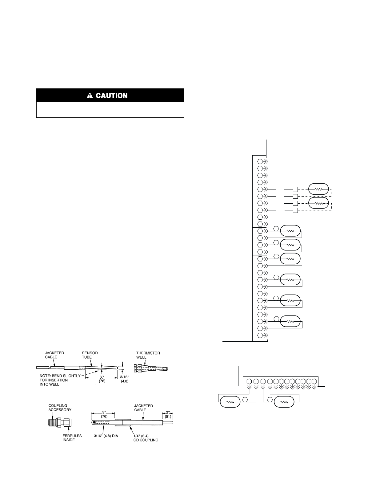
Fig. 32 — Thermistors (Temperature Sensors)
X = T1,T5,T6 = 3
″
(76)
T7,T8 = 4
″
(102)
1
2
3
4
1
2
3
4
26
25
24
23
22
21
20
19
18
17
16
15
14
13
12
11
10
9
8
7
6
5
BLU
BLU
PNK
PNK
TB5
TB5
TB5
TB5
5
6
7
8
T10
T9
REMOTE SPACE TEMP
(ACCESSORY)
5
6
7
8
9
10
1
2
3
4
1
2
3
4
5
6
1
2
3
4
5
6
2
1
4
6
3
5
T5
T3
T4
T6
T2
T1
COOLER ENTERING
FLUID TEMP
OUTDOOR-AIR TEMP
(ACCESSORY) OR
DUAL CHILLER LWT
COOLER LEAVING
FLUID TEMP
SATURATED
CONDENSING TEMP-
CIRCUIT B
SATURATED
SUCTION TEMP-
CIRCUIT B*
SATURATED
CONDENSING TEMP-
CIRCUIT A
SATURATED
SUCTION TEMP-
CIRCUIT A*
MAIN BASE BOARD
J8
T1-T6, T9, T10 THERMISTORS
J5
EXV BOARD
12
11
10 9
8
7
6
5
4
32
1
12
11 10 9
T8
8
T7
7
CKTA* CKTB*
COMPRESSOR RETURN GAS TEMP
T7, T8 THERMISTORS
LEGEND
*Not used on units with TXV (Thermostatic Expansion Valve) FIOP
(Factory-Installed Option).
Fig. 33 — Thermistor Connections to J5 and J8
Processor Boards
LWT —
Leaving Fluid Temperature


