17
The capacity control algorithm runs every 30 seconds. The
algorithm attempts to maintain the leaving chilled water tem-
perature at the control point. Each time it runs, the control reads
the entering and leaving fluid temperatures. The control deter-
mines the rate at which conditions are changing and calculates
2 variables based on these conditions. Next, a capacity ratio is
calculated using the 2 variables to determine whether or not to
make any changes to the current stages of capacity. This ratio
value ranges from –100 to + 100%. If the next stage of capacity
is a compressor, the control starts (stops) a compressor when
the ratio reaches +100% (–100%). If the next stage of capacity
is an unloader, the control deenergizes (energizes) an unloader
when the ratio reaches +60% (–60%). Unloaders are allowed to
cycle faster than compressors, to minimize the number of starts
and stops on each compressor. A delay of 90 seconds occurs af-
ter each capacity step change.
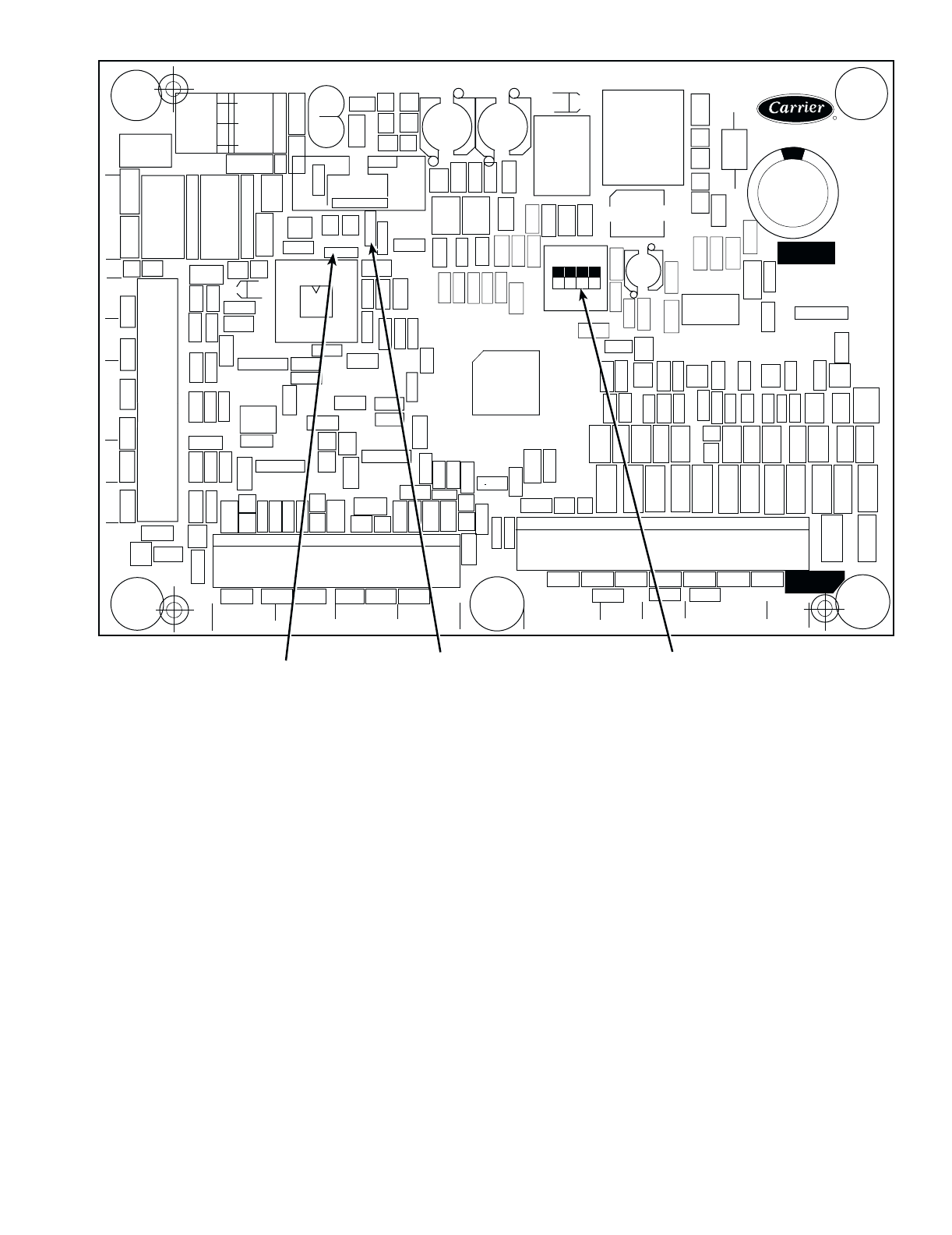
CEBD430351-0396-01C
TEST 1
CEPL130351-01
PWR
TEST 2
J1
J2
J4 J3
J5
J6
J7
LEN
STATUS
RED LED - STATUS
GREEN LED -
LEN (LOCAL EQUIPMENT NETWORK)
ADDRESS
DIP SWITCH
Fig. 16 — Energy Management Module


