


18
SECTION 7: MAINTAINING MOWER DECK
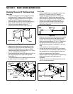
Checking The Level Of The Mower Deck
Side to Side
• Position the Z-Series on a hard and level surface
and place the PTO switch in the OFF position.
• Engage the parking brake and turn the ignition
switch to the OFF position and remove key.
• Remove spark plug wire(s) from the spark plug(s).
• Raise the lift handle to the highest setting (7).
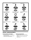
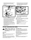
• Position the mower blades so they run
perpendicular to the Z-Series. See Figure 18.
Figure 18
• Measure the distance from the outside of the left
blade tip to the ground and the distance from the
outside of the right blade tip to the ground. Both
measurements taken should be within 1/16”. If they
are not, proceed to the next step.
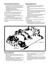
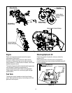
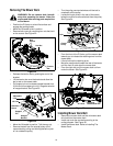
• Remove the shoulder screw that holds the lift link to
the hanger bracket on the side to be adjusted.
See Figure 19.
• Turn the adjustable link the appropriate distance up
or down. Every 1/2 turn equals 1/32”.
Figure 19
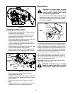
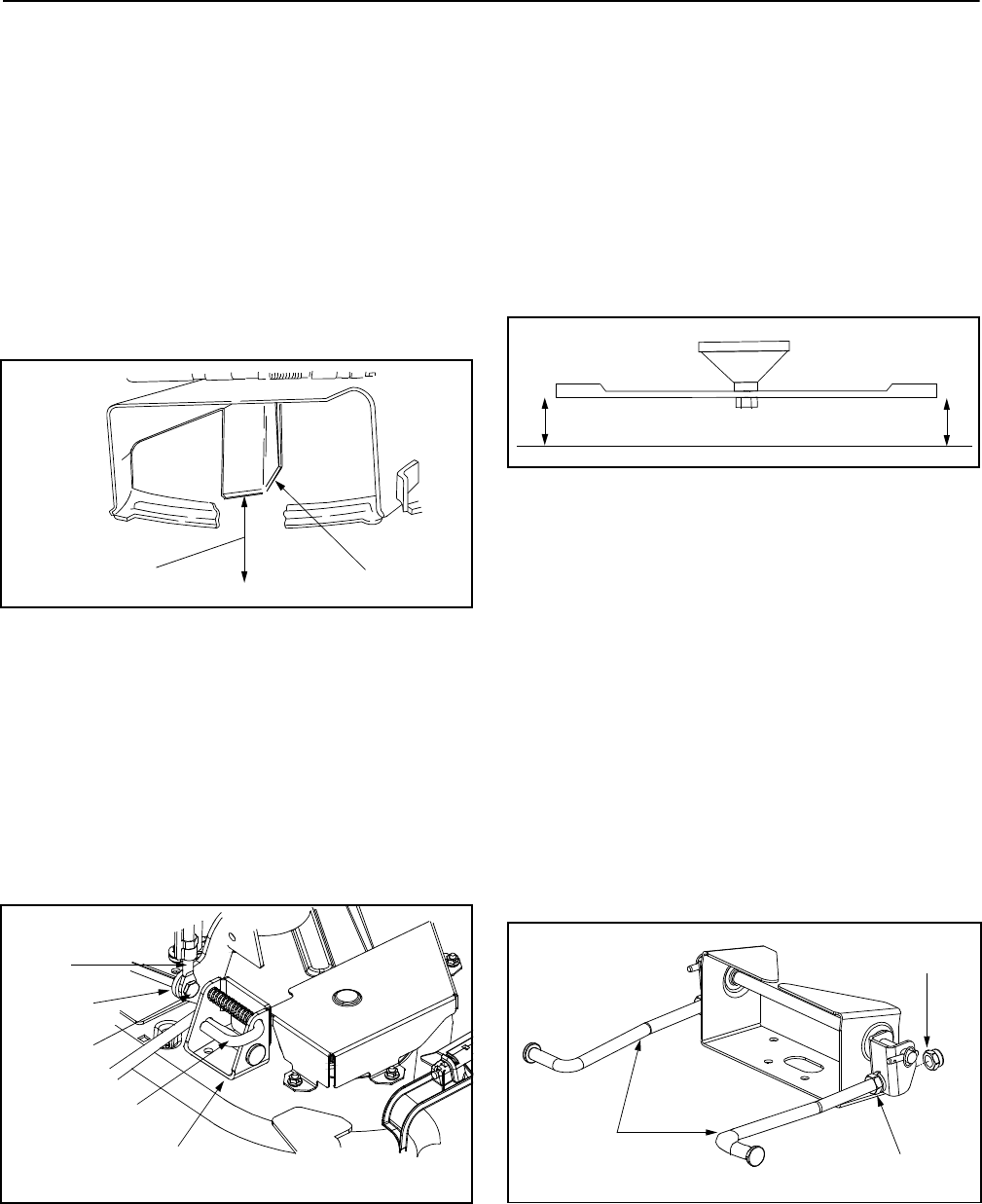
Front To Rear
• Position the Z-Series on a hard level surface and
place the PTO switch in the OFF position.
• Engage the parking brake and turn the ignition
switch to the OFF position and remove the key.
• Remove spark plug wire(s) from the spark plug(s).
• Raise the lift handle to the highest setting (7).
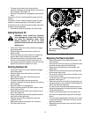
• Position the mower blades so the ends of each
blade point to the front and to the rear of the Z-
Series. See Figure 20.
Figure 20
• Measure the distance from the front of the blade tip
to the ground and the rear of the blade tip to the
ground. The front edge of each blade should be
lower than its back edge by 1/8” to 1/4”. Determine
the appropriate distance necessary for proper
adjustment and proceed, if necessary, to the next
step.
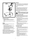
• Lower the deck to the lowest position.
• Loosen the rear jam nuts on the front lift rods and
turn the front lock nuts clockwise to raise the front of
the mower deck or counterclockwise to lower the
front of the mower deck. See Figure 21.
• Raise the deck to the highest position. Recheck the
blade measurements and repeat steps, if
necessary.
• Tighten the rear jam nuts after adjustments of the
front lift rods are completed.
Figure 21
Measurement
Blade
Adjustable
Link
Lift Link
Shoulder
Screw
Support
Pin
Hanger
Bracket
Rear
Edge
Front
Edge
Front Lift
Rods
Lock Nut
Jam Nut