


5
SECTION 2: ASSEMBLING YOUR SNOW THROWER
Unpacking
• Remove screws from the top sides and ends of the
shipping crate.
• Set panel aside to avoid tire punctures or personal
injury.
• Remove and discard plastic bag that covers unit.
• Roll unit out of crate.
• Check crate thoroughly for loose parts before
discarding.
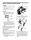
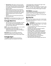
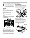
Loose Parts
• The snow thrower is shipped with following loose
parts in the carton. See Figure 1 for illustration,
description of item and part number. Please
remove all loose parts from the carton before
discarding it.
Figure 1
• Please note that these shear bolts and hex lock
nuts are not meant for initial assembly of the
equipment. If the snow thrower hits a foreign object
or ice jam, the bolts, securing the auger shaft, may
shear. Use these two shear bolts and nuts as
replacement then. Store these in a safe place until
needed.
IMPORTANT:
NEVER replace the auger shear bolts with
standard hex bolts. Any damage to the auger gearbox
or other components from standard hex bolts will not be
covered by your snow thrower’s warranty.
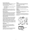
Assembling Handle
NOTE: Reference to the left or right side of the snow
thrower in this manual is observed from the operator’s
position.
IMPORTANT:
Make any final adjustments, as instructed
later on in this section, before operating your snow
thrower. Failure to follow these instructions may cause
damage to the snow thrower.
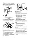
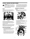
• Remove the lower plastic wing nut, cupped washer
and carriage bolt from each side of the lower
handle. See Figure 2.
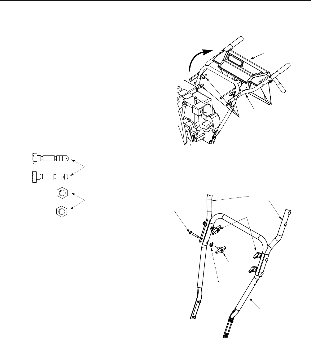
Figure 2
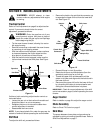
• Raise the upper handle assembly in the direction
shown in Figure 2. Make sure that the upper handle
locks into position over the lower handle.
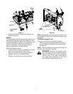
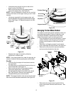
Figure 3
• Look at lower rear of snow thrower frame to be sure
all cables are aligned with cable roller guides.
• Secure the upper handle and lower handle with the
two plastic wing nuts, cupped washers and carriage
bolts previously removed. Attach these hardware
on the lower hole in the handles. See Figure 3.
• Tighten the two wing nuts already in place on the
upper holes and secure the handles firmly. See
Figure 3.
Shear Bolts
(710-0890A)
Hex Lock Nuts
(712-0429)
Wing Nuts,
Washers
and Bolts
Upper Handle
Handle Panel
Wing
Cupped
Carriage
Bolt
Upper
Lower
Nut
Washer
Handle
Handle
Tighten these
wing nuts