


12
SECTION 5: MAKING ADJUSTMENTS
WARNING: NEVER attempt to clean
chute or make any adjustments while engine
is running.
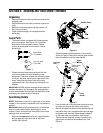
Traction Control
Refer to Final Adjustments on page 6 to adjust traction
control. If you want to check further for correct
adjustment, proceed as follows:
WARNING: Drain the gasoline out of your
snow thrower’s engine, and place a piece of
plastic film under the gas cap to avoid spillage
before beginning the job.
• Tip the snow thrower forward, allowing it to rest on
the auger housing.
• Remove frame cover underneath the snow thrower
by removing six self-tapping screws.
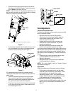
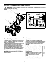
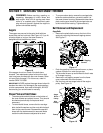
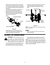
• With the traction control released, make sure there
is clearance between the friction wheel and the
drive plate in all positions of the shift lever.
• With the traction control engaged, make sure the
friction wheel contacts the drive plate. See Figure
11.
Figure 11
If either or both are lacking, adjust traction control as
instructed below:
• Loosen the jam nut on the traction drive cable and
thread the cable in or out as necessary.
• Retighten the jam nut to secure the cable when
correct adjustment is reached.
• Reassemble the frame cover.
NOTE: If you placed plastic film under the gas cap, be
certain to remove it before operating the snow thrower.
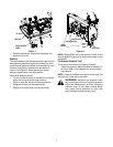
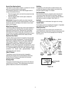
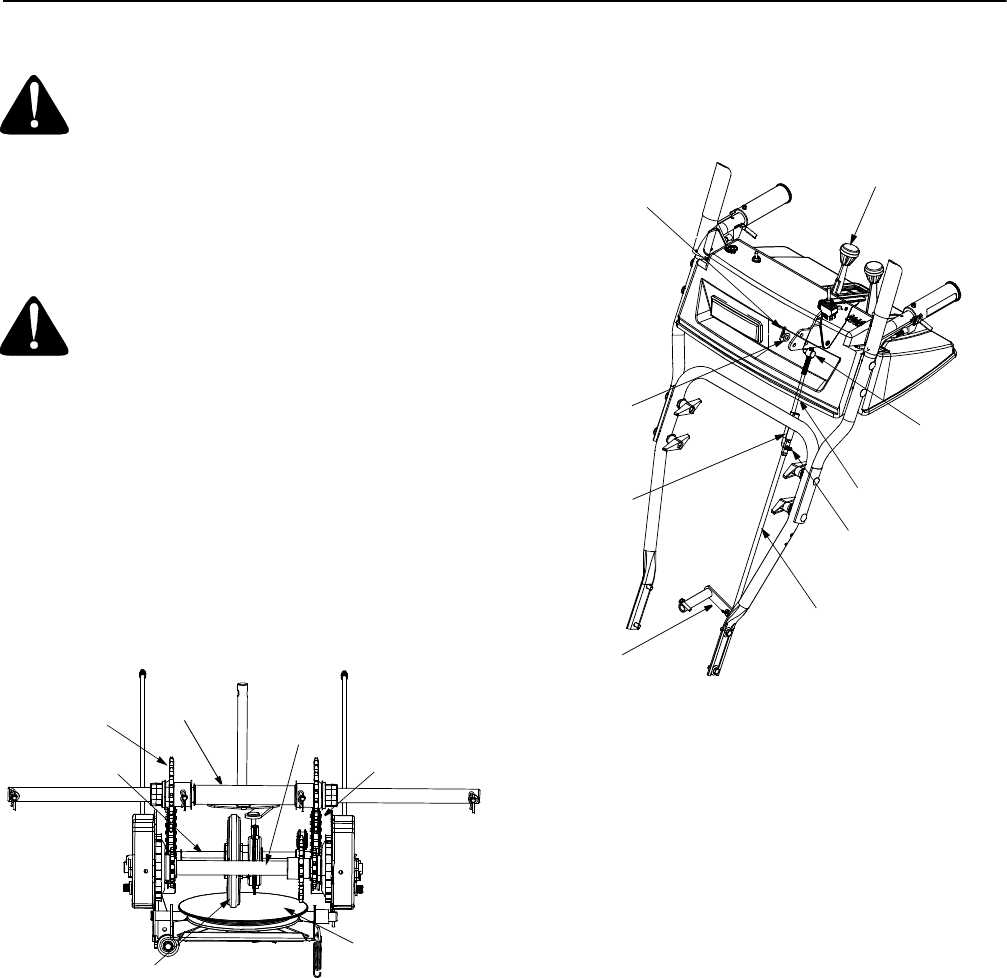
Shift Rod
To adjust the shift rod, proceed as follows.
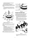
• Remove the hairpin clip and slide the connector up
to separate the upper shift rod from the lower shift
rod. See Figure 12.
Figure 12
• Place shift lever in sixth (6) position.
• Rotate the shift arm counterclockwise (from the
operator’s position) as far as it will go.
• Thread the upper shift rod downward until the
elbow on its lower end aligns with the hole found in
the lower shift rod.
• Reconnect the upper shift rod to the lower shift rod
by reinserting the cotter pin removed earlier and
sliding the connector back down into place.
IMPORTANT:
Check for correct adjustment of the shift
rod as instructed on page 6, before operating the snow
thrower.
Auger Control
Refer to details on page 6 to adjust the auger control.
Chute Assembly
Refer to Chute Tilt Control on page 9.
Skid Shoe
The space between shave plate and ground can be
adjusted by raising or lowering the skid shoes. Refer to
Skid Shoe Adjustment on page 7.
Drive Shaft
Friction Wheel
Drive Plate
Hex Shaft
Axle Shaft
Chain
Sprocket
Shift Lever
Ferrule
Shift Arm
Hairpin
Clip
Lower Shift Rod
Clutch Rod
Upper Shift Rod
Connector
Hairpin Clip
Flat
Washer