


15
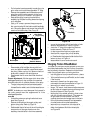
• Pull the brake bracket assembly towards the cable
guide roller and unhook the auger cable “Z” fitting.
• Remove the upper bolts and lock washers which
attach the auger housing assembly to the frame
assembly using a 9/16” wrench. See Figure 16.
• Separate the auger housing from the frame
assembly by tilting the housing forward and pulling
up the handles.
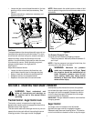
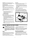
• Using a 1/2” wrench, remove the hex screw and
belleville washer from the center of the pulley on
the auger housing. Lift the brake bracket assembly
out of the pulley groove and remove the pulley. Be
careful not to lose the key. See Figure 18.
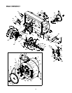
Figure 18
• Remove and replace auger belt inside belt keepers.
• Reassemble pulley to auger housing with hex
screw and belleville washer (cupped side toward
the pulley). Make sure key is in place on shaft and
brake puck is seated in the pulley groove.
• Reassemble the belt cover and chute directional
control.
Proper Adjustment: With the auger clutch lever in the
disengaged position the top surface of the new belt
should be even with the outside diameter of the pulley.
• To adjust, disconnect ferrule from brake bracket
assembly and thread ferrule in (towards idler) to
increase tension on belt, and out to decrease tension.
NOTE: The brake puck must always be firmly seated in
the pulley groove when the auger control is in the
disengaged position.
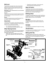
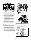
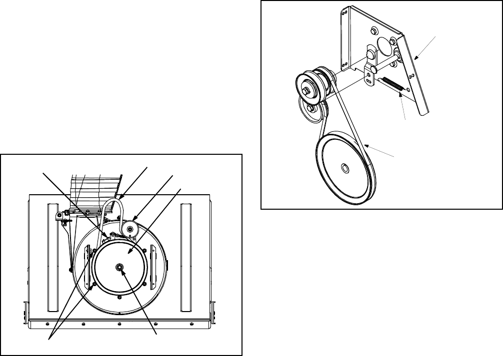
Drive Belt
• Unhook the extension spring from the belt cover
plate. See Figure 19.
• Remove drive belt from the engine pulley and
bottom drive pulley. Refer to Figure 19.
• Replace belt and reassemble in reverse order.
• Reassemble the two halves of the unit hooking the
lower portion of the auger housing over the
stationary shoulder bolts in the frame assembly.
Figure 19
• Secure the two halves with the two bolts and lock
washers removed earlier. Refer to Figure 16.
• Attach the “Z” fitting of the cable into the brake
bracket assembly. Refer to Figure 17.
• Slip the auger control belt over engine pulley.
• Insert ferrule on auger idler rod into bracket
assembly and secure with flat washer and cotter
pin. Reassemble the large shoulder bolt and lock
washer as shown in Figure 16.
• Reassemble belt cover and chute crank.
Changing Friction Wheel Rubber
The rubber on the friction wheel is subject to wear and
should be checked after the first 25 hours of operation,
and periodically thereafter. Replace the friction wheel
rubber if any signs of wear or cracking are found.
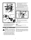
• Drain the gasoline from the snow thrower, or place
a piece of plastic under the gas cap.
• Tip the snow thrower up and forward, so that it rests
on the housing.
• Remove six screws from the frame cover
underneath the snow thrower. Refer to Figure 10.
• Remove the left wheel from the axle.
• Using a 7/8” wrench, hold the hex shaft and remove
the hex bolts and cupped washer and bearing from
left side of the frame. See Figure 20.
• Holding the friction wheel assembly, slide the hex
shaft out of the left side of the unit. The spacer on
the right side of the hex shaft will fall and the
sprocket should remain hanging lose in the chain.
• Lift the friction wheel assembly out between the
axle shaft and the drive shaft assemblies.
• Remove the six screws from both sides of the
friction wheel assembly and remove friction wheel
rubber from between the friction wheel plate.
See Figure 20.
Brake Bracket Assembly
Auger Belt
Hex Screw
Belleville Washer
Belt Keepers
Auger Pulley
Idler Pulley
Drive Belt
Extension
Spring
Belt Cover