


11
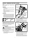
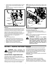
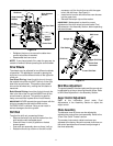
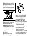
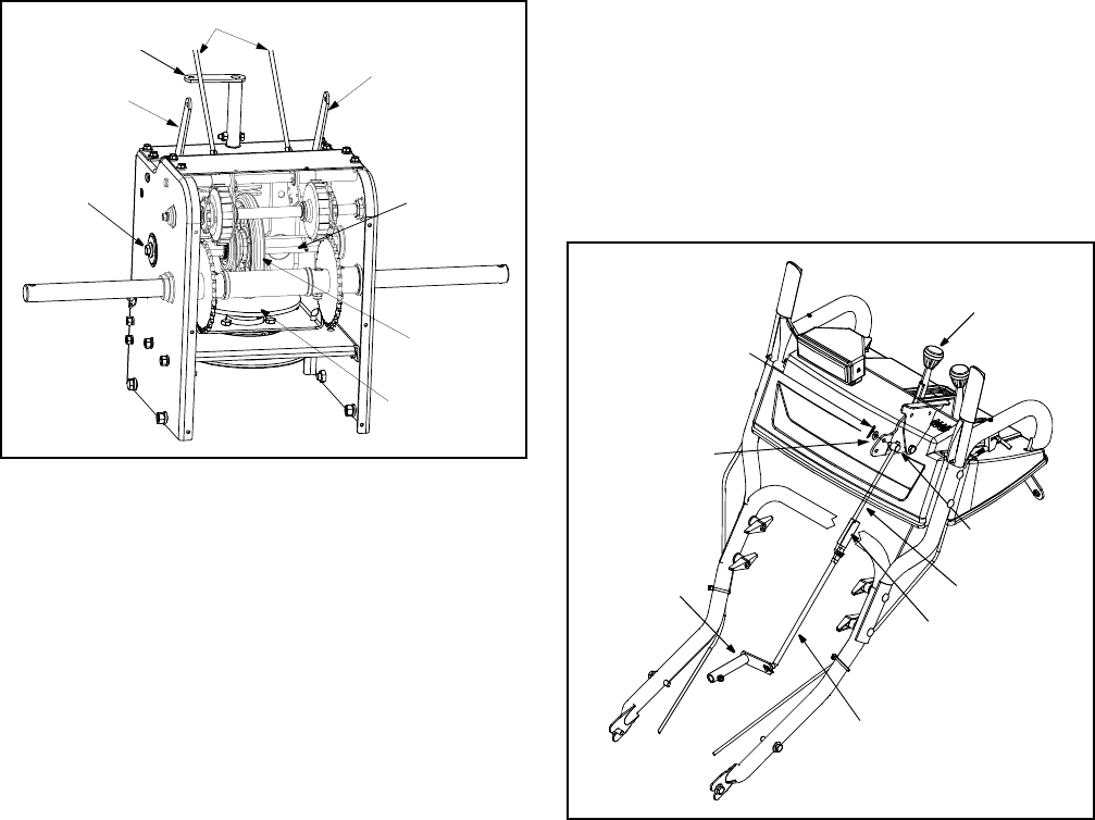
Figure 10
• Retighten the jam nut to secure the cable when
correct adjustment is reached.
• Reassemble the frame cover.
NOTE: If you placed plastic film under the gas cap, be
certain to remove it before operating the snow thrower.
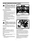
Drive Wheels
The wheels may be adjusted for two different methods
of operation. The adjustment is made by placing the
click pins in one of two different holes on the right side
of the unit.
One Wheel Driving: Insert the click pin only through
the outside hole of the axle (NOT the rim) on the right
side of the snow thrower. This position gives power
drive to the left wheel only, making the unit easier to
maneuver.
Both Wheels Driving: Insert the click pin through the
hole in the hub of the rim and the INSIDE hole on the
snow thrower’s right axle. This position is good for
heavy snow as there is power drive in both wheels.
IMPORTANT:
NEVER operate the snow thrower with the
click pin inserted through both the RIM and the
OUTSIDE HOLE in the axle. Doing so can result in
serious damage to the drive system.
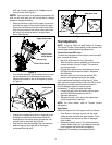
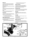
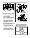
Shift Rod
To adjust the shift rod, proceed as follows:
• Remove the hairpin clip and flat washer from the
shift handle under the handle panel.
• Place shift lever in sixth (6) position or fastest
forward speed.
• Push shift arm assembly down as far as it will go.
• Rotate the ferrule up or down on the shift rod as
necessary until the ferrule lines up with the upper
hole in the shift lever. See Figure 11.
• Insert ferrule from the left side of the snow thrower
into the upper hole.
• Reinstall the hairpin clip and the washer.
IMPORTANT:
Make certain to check for correct
adjustment of the shift rod as instructed under Final
Adjustments in the Assembly Section, before operating
the snow thrower.
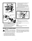
Figure 11
Skid Shoe Adjustment
The space between the shave plate and the ground can
be adjusted by raising or lowering the skid shoes. Refer
to Skid Shoe Adjustment in the Assembly Section.
Auger Control Adjustment
Refer to the information found under Final
Adjustments in the Assembly Section to adjust the
auger control.
Chute Assembly
The distance snow is thrown can be adjusted by
adjusting the angle of the chute assembly. Refer to the
“Know Your Snow Thrower” section.
The remote chute control cables have been pre-
adjusted at the factory. Move the remote chute lever on
the control panel back and forward to adjust angle of
the chute assembly.
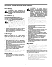
Trigger Cables
Shift Arm
Drive Actuator
Auger Actuator
Hex Nut
Hex Gear Shaft
Drive Plate
Rubber
Bracket
Bracket
And Cupped
Washer
Friction
Wheel
Shift Lever
Ferrule
Shift Arm
Lower Shift Rod
Clutch Rod
Upper Shift Rod
Connector
Hairpin Clip
Flat Washer