


11
MAINTENANCE AND REPAIR INSTRUCTIONS
SERVICING DOUBLE INSULATED UNITS
This unit is double-insulated. In a double-insulated unit,
two systems of insulation are provided instead of
grounding. There is no grounding provided and no
means of grounding should be added to this unit.
Extreme care and knowledge of the system is required
when servicing a double-insulated unit. Service should
be performed by qualified service personnel only.
Replacement parts for a double-insulated unit must be
identical to the parts they replace. Refer any repair to an
authorized service dealer. A double-insulated unit is
marked with the words “double insulation” or “double
insulated.”
LINE INSTALLATION FOR THE SPEEDSPOOL
®
Always use original equipment manufacturer 0.080 inch
(2.03 mm) replacement line. Line other than the specified
may make the motor overheat or fail.
There are two methods to replace the SpeedSpool
®
trimming line:
• Wind the inner reel with new line
• Install a pre-wound inner reel
Winding the Inner Reel With New Line
NOTE: It Is unnecessary to remove the bump knob to
install a new trimming line.
1. Cut two pieces of 0.080 inch (2.03 mm) trimming
line, 10 feet (3 m) long.
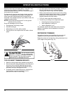
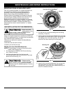
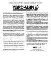
2. Hold the outer spool and turn the inner reel
counterclockwise to line up the arrows on the outer
spool and inner reel (Fig. 14).
Top View Of The SpeedSpool
®
Outer Spool
Inner Reel
Fig. 14
Bump Knob
Arrows
Never use metal-
reinforced line, wire,
chain or rope. These can break off and
become dangerous projectiles.
WARNING:
Always use the
correct line length
when installing trimming line on the unit.
The line may not release properly if the line
is too long.
WARNING:
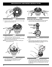
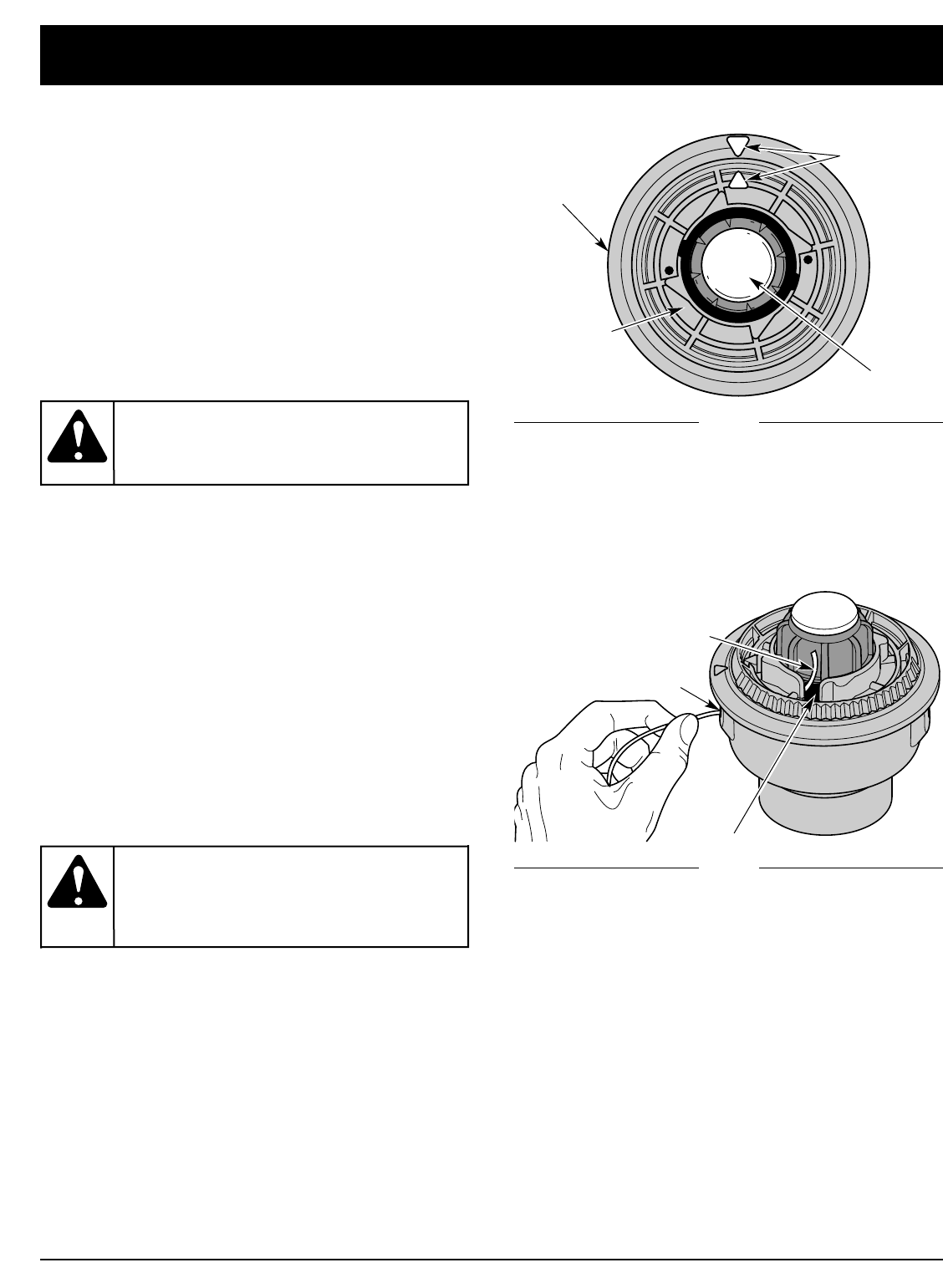
Trimming Line
Line Loading Hole
Eyelet
5. Insert the line into the locking hole. Do not push the
line more than a 1/2 inch (12.7 mm) into the line
locking hole. The line will form a small loop (Fig. 16)
when it is inserted correctly.
3. Pull old line out of the line loading and line locking
holes (Fig. 14 and 15).
4. Insert a piece of trimming line straight into one of the
two eyelets in the outer spool. Push it up through the
line loading hole in the inner reel (Fig. 15). Do not
bend the line when inserting it into the eyelet.
Fig. 15