


5
SECTION 4: ASSEMBLY
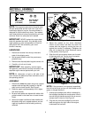
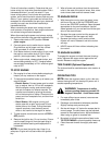
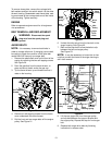
AUGER SHEAR BOLTS (SPARES)
NOTE: The augers are secured to the spiral shaft
with two shear bolts and hex lock nuts. If you hit a
hard foreign object or ice jam, the snow thrower is
designed so that the bolts may shear. Two replace-
ment shear bolts and nuts are provided for your con-
venience. Store in a safe place until needed.
IMPORTANT: NEVER replace the auger shear
bolts with standard hex bolts. Any damage to the
auger gearbox or other components as a result of
doing so will NOT be covered by your snow
thrower’s warranty.
UNPACKING
1. Remove the screws from the top, sides and
ends of the shipping crate.
2. Set top panel aside to avoid tire punctures or
personal injury.
3. Remove and discard plastic bag that covers unit.
4. Carefully roll unit out of crate.
IMPORTANT: After assembly, service engine
with gasoline, and check oil level as instructed in the
separate engine manual packed with your unit.
NOTE: All references to right or left side of the
snow thrower are determined from behind the unit in
the operating position.
ASSEMBLY
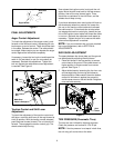
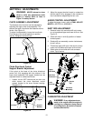
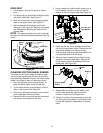
1. Remove the lower two plastic wing nuts, cupped
washers and carriage bolt (eyebolt on the left
side) from the lower handle. See Figure 3.
2. Raise the upper handle assembly until it aligns
with lower handle.
3. Be sure both cables are aligned with cable roller
guides located in the lower rear of snow thrower
frame.
4. Secure the upper handle and lower handle with
the plastic wing nuts, cupped washers, and car-
riage bolt (eyebolt on the left side) previously
removed.
Figure 3
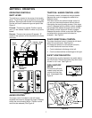
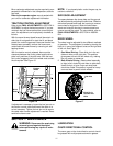
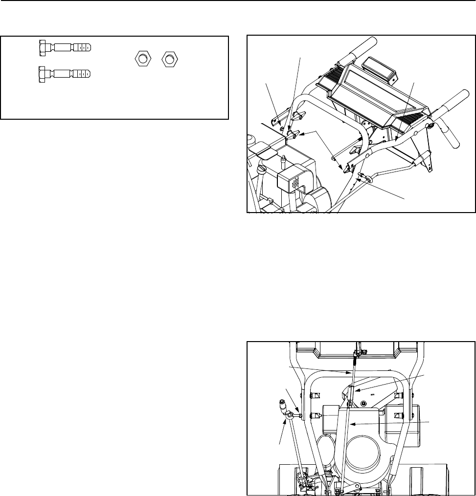
5. Adjust the eyebolt on the chute directional
control so the control rod does not come into
contact with the engine by moving the hex nut
against the handle (if necessary). Retighten the
wing nut to secure the chute directional control
in this position. See Figure 4.
6. Slide the shift rod connector down over the end
of the lower shift rod. Tap the top of connector
until it locks on the lower shift rod.
Figure 4
NOTE: If the connector is not properly assembled,
the shift rod will pivot and you will not be able to shift
gears or change directions.
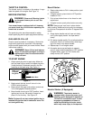
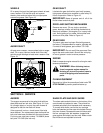
7. Unwrap the headlight wire which is attached to
the headlight, beneath the handle panel. Wind it
around the right handle several times to remove
excess slack in the wire. See Figure 5.
8. Plug the wire from the headlight into the wire
lead coming from the right side of the engine,
underneath the fuel tank.
Shear Bolts
(710-0890A)
(712-0429)
Hex Lock Nuts
5/16” Thread
Wing
Nuts
Carriage
Bolt
Cupped
Washer
Lower
Handle
Upper
Handle
Shift Rod
Upper
Shift Rod
Lower
Shift Rod
Connector
Hex Nut
Eyebolt