


10
SECTION 6: ADJUSTMENTS
WARNING: NEVER attempt to clean
chute or make any adjustments while
engine is running. Refer to label in
Figure 2 in safety section.
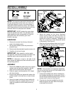
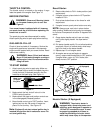
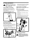
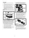
CHUTE ASSEMBLY ADJUSTMENT
The distance snow is thrown can be adjusted by
adjusting the angle of the chute assembly. The
sharper the angle, the shorter the distance snow is
thrown. See Figure 13.
To adjust chute assembly, loosen the hand knob.
Pivot the top of the chute assembly to position
desired. Retighten the hand knob.
Figure 13
Chute Directional Control
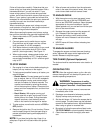
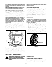
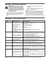
Support Bracket Adjustment
If the spiral at the base of the chute directional
control isn’t fully engaging with the notches in the
lower chute assembly, the support bracket can be
adjusted inward or outward as follows:
1. Loosen, but do NOT remove the two hex nuts
which secure the chute directional control
support bracket to the snow thrower housing.
See Figure 14.
Figure 14
2. Adjust the support bracket inward or outward so
that the spiral is fully engaged in the notches on
the chute before retightening the hex nuts.
AUGER CONTROL ADJUSTMENT
To adjust the auger control, refer to FINAL ADJUST-
MENTS in SECTION 4: ASSEMBLY.
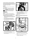
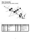
SHIFT ROD ADJUSTMENT
1. Remove hairpin clip and slide shift rod connec-
tor up to separate upper and lower shift rod. See
Figure 15.
2. Place shift lever in sixth (6) position or fastest
forward speed.
3. Rotate shift arm assembly counter clockwise as
far as it will go.
4. Thread the upper shift rod on the ferrule to align
upper shift rod elbow with lower shift rod hole.
5. Insert cotter pin and slide shift rod connector
down. Tap to secure.
Figure 15
CARBURETOR ADJUSTMENT
WARNING:
If any adjustments are
made to the engine while the engine is
running (e.g. carburetor), keep clear of
all moving parts. Be careful of heated
surfaces and muffler.
Hand Knob
Hex Nuts
Support
Spiral
Bracket
Shift
Lever
Ferrule
Upper
Shift Rod
Hairpin
Clip
Shift Rod
Connector
Lower
Shift Rod
Shift Arm
Assembly