


11
Minor carburetor adjustment may be required to com-
pensate for differences in fuel, temperature, altitude
and load.
Refer to the separate engine manual packed with
your unit for carburetor adjustment information.
TRACTION CONTROL ADJUSTMENT
Refer to the FINAL ADJUSTMENTS in SECTION 4:
ASSEMBLY to adjust the traction control. If you are
uncertain that you have reached the correct adjust-
ment, the adjustment can be physically checked as
follows.
With the snow thrower tipped forward (be certain to
drain the oil and gasoline or drain the oil and place
plastic film under the gas cap if the snow thrower has
already been operated), remove the frame cover
underneath the snow thrower by removing six self-
tapping screws.
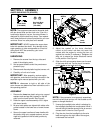
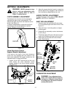
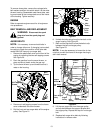
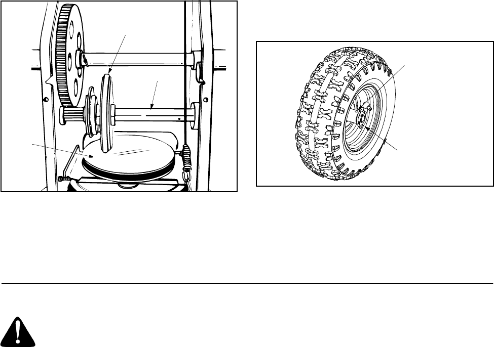
With the traction control released, there must be
clearance between the friction wheel and the drive
plate in all positions of the shift lever. With the trac-
tion control engaged, the friction wheel must contact
the drive plate. See Figure 16.
Figure 16
If adjustment is necessary, loosen the hex jam nut on
the traction control cable and thread the cable in or
out as necessary. Tighten the hex jam nut to secure
the cable when correct adjustment is reached. Reas-
semble the frame cover.
NOTE: If you placed plastic under the gas cap, be
certain to remove it.
SKID SHOE ADJUSTMENT
The space between the shave plate and the ground
can be adjusted by adjusting the skid shoe. Slide the
skid shoe upwards and lower the housing to remove
snow close to the ground. Slide skid shoe down-
wards and raise the housing to remove snow from
uneven ground like gravel. For more details, refer to
FINAL ADJUSTMENTS in SECTION 4: ASSEM-
BLY.
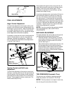
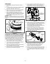
DRIVE WHEEL
The wheel may be adjusted for two different methods
of operation. The adjustment is made by placing the
klick pin in one of two different holes on the right side
of the unit. See Figure 17.
1. One Wheel Driving - Place klick pin in the out-
side axle hole on the right side. This position
gives power drive to the left wheel only, making
the unit easier to maneuver.
2. Both Wheels Driving - Rotate wheel assembly
to align hole in hub with inner hole on axle shaft.
Insert klick pin in hole. Outer axle shaft hole
should be visible.This position is good for heavy
snow as there is power to both wheels.
Figure 17
SECTION 7: MAINTENANCE
WARNING: Disconnect the spark plug
wire and ground against the engine
before performing any repairs or main-
tenance.
LUBRICATION
CHUTE DIRECTIONAL CONTROL
The worm gear on the chute direction control should
be greased with multipurpose automotive grease.
Friction
Wheel
Gear Shaft
Drive
Plate
Hub Hole
Klick Pin In
Outside Axle
Hole