


7
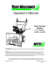
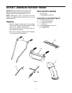
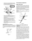
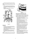
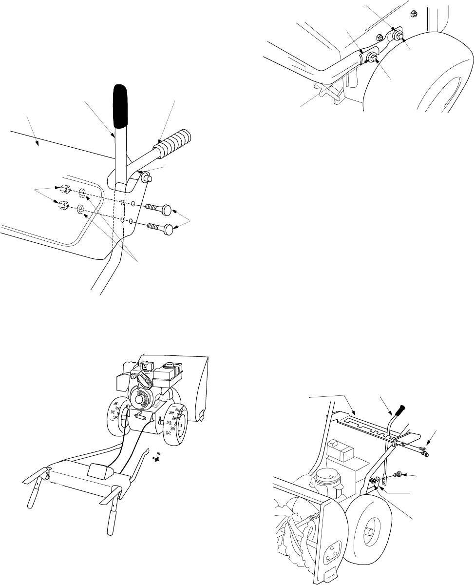
Assembling the handles and handle
panel (hardware a and b)
• Raise both clutch grips.
• Lower left and right handles (A) down through
handle panel (B) between the pivot rod and the
clutch grips and attach using hardware B. See
Figure 2.
Figure 2
• Do not tighten at this time.
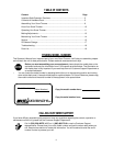
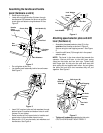
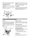
• Lay handle panel assembly behind snow thrower.
See Figure 3.
Figure 3
• Insert 3/4” long hex bolts and lock washers through
bottom holes in handles and bottom holes in snow
thrower. Do not tighten.
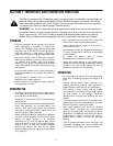
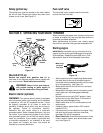
• Raise handles up until upper holes in handles and
upper holes in snow thrower frame line up.
• Secure with 1 3/4” long hex bolts, lock washers and
handle tabs. See Figure 4.
Figure 4
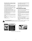
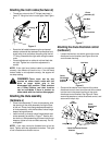
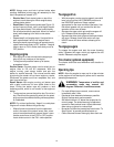
Attaching speed selector plate and shift
lever (hardware c)
• Assemble the speed selector plate (C) to the
outside of the handles as shown in Figure 5.
Secure using four self-tapping screws. See Figure
5.
• Insert the shift lever (D) through slot in the speed
selector plate.
NOTE:
The bend in the lever should be towards the
operator. Secure shift lever to the shift lever spring
using two hex bolts and hex lock nuts. Tighten both
bolts finger tight. At this point the shift lever and shift
lever spring are not against each other. As you tighten
the bolts and nuts with two wrenches they will pull
together. See Figure 5.
Figure 5
• Tighten all hardware assembled to this point.
CLUTCH GRIPS MUST MOVE FREELY.
Carriage
Bolts
Lock Washers
Hex
Nuts
Clutch Grip
Pivot Rod
Left Handle (A)
Handle
Panel
Assembly(B)
Lock Washer
Lock Washer
Hex Bolt
Hex Bolt
Handle
Tabs
Speed
Selector
Plate (C)
Shift Lever (D)
Self-Tapping
Screw
Shift Lever
Spring
Hex Bolts
Hex Lock
Nuts