


16
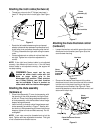
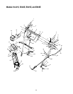
• Unhook the support bracket spring from the frame.
NOTE:
It may be necessary to loosen the six nuts that
connect the frame to the auger housing to aid in belt
removal.
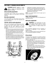
• Lift the rear auger belt from the auger pulley, and
slip belt between the support bracket and the auger
pulley. See Figure 22. Repeat this step for the front
auger belt.
• Replace both auger control belts by following
instructions in reverse order.
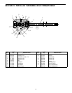
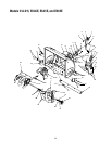
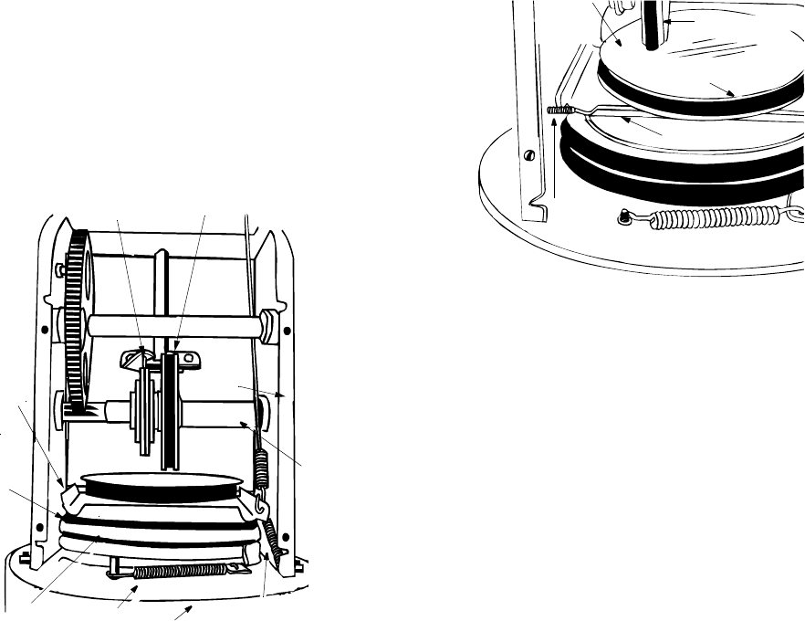
Figure 23
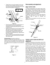
Drive belt
• Follow steps 1 through 4 of previous instructions.
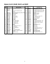
• Pull idler pulley up, and lift belt off engine pulley and
friction wheel disc. See Figure 22.
• Using an adjustable wrench, loosen the nut on the
stop bolt until the support bracket rest on the auger
pulley. See Figure 24.
• Slip belt between friction wheel and friction wheel
disc. See Figure 24. Remove and replace belt.
Reassemble, following the instructions in reverse
order.
NOTE:
The support bracket must rest on the stop bolt
after the new belt has been assembled. See Figure 24.
Figure 24
Changing the friction wheel rubber
The rubber on the friction wheel is subject to wear and
should be checked after 25 hours of operation, and
periodically thereafter. Replace the friction wheel
rubber if any signs of wear or cracking are found.
• Drain the gasoline from the snow thrower, or place
a piece of plastic under the gas cap.
• Tip the snow thrower up and forward, so that it rest
on the housing.
• Remove six self-tapping screws from the frame
cover underneath the snow thrower.
• Remove the klick pins which secure the wheels,
and remove the wheels from the axle.
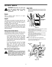
• Using an adjustable wrench to hold the shaft,
loosen, but do not completely remove, the hex nut
and bell washer on the left end of gear shaft. See
Figure 25.
• Lightly tap the hex nut to dislodge the ball bearing
from the right side of the frame. Remove the hex
nut and bell washer from the left end of shaft.
• Slide the gear shaft to the right, then slide the
friction wheel assembly from the shaft.
• Remove the six screws from the friction wheel
assembly (three from each side). Remove the
friction wheel rubber from between the friction
wheel plate.
• Reassemble new friction wheel rubber to the
friction wheel assembly, tightening the six screws in
rotation and with equal force.
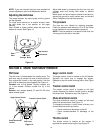
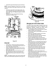
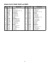
• Slide friction wheel assembly back onto the gear
shaft. Be sure to align the pin on the shift rod with
the hole in the friction wheel assembly. See Figure
23. Reassemble in reverse order.
Pin
Friction Wheel
Assembly
Frame
Auger
Belt
Auger
Pulley
Idler
Spring
Auger
Housing
Support
Bracket
Spring
Support
Bracket
Gear
Shaft
Friction
Wheel
Disc
Stop
Bolt
Support Bracket
Drive Belt
Friction Wheel