


• Thread the front speed control link in or out of the
ferrule until the hole in the link lines up with the pin
on the variable speed torque bracket. Secure with
the flat washer and cotter pin removed earlier.
• Push the rear speed control linkbackward using
light pressure, and hold it inthis position as you
thread it into or out of the ferrule until the hole in the
link lines up with the pin on the variable speed
torque bracket.
• Models 820 thru 829 Only: Turn the link three
more times (making it longer).
• Move the speed control lever toward the right so
'the _,o_ein the rear speed oo_tro__inkf_t_ever the
pin on the variable speed torque bracket. Secure
with the flat washer and cotter pin removed eadier.
• Remove the 3/4" shim from beneath the bracket on
the clutch-brake pedal.
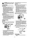
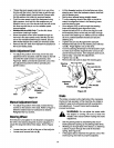
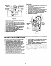
QuickAdjustmentSeat
• To adjust the position of the seat, move the seat
adjustment lever (located under the seat} to the left
and slide the seat forward or backwards. See
Figure 24. Make sure seat is locked into one of the
six adjustment positions before operating the
garden tractor.
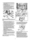
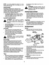
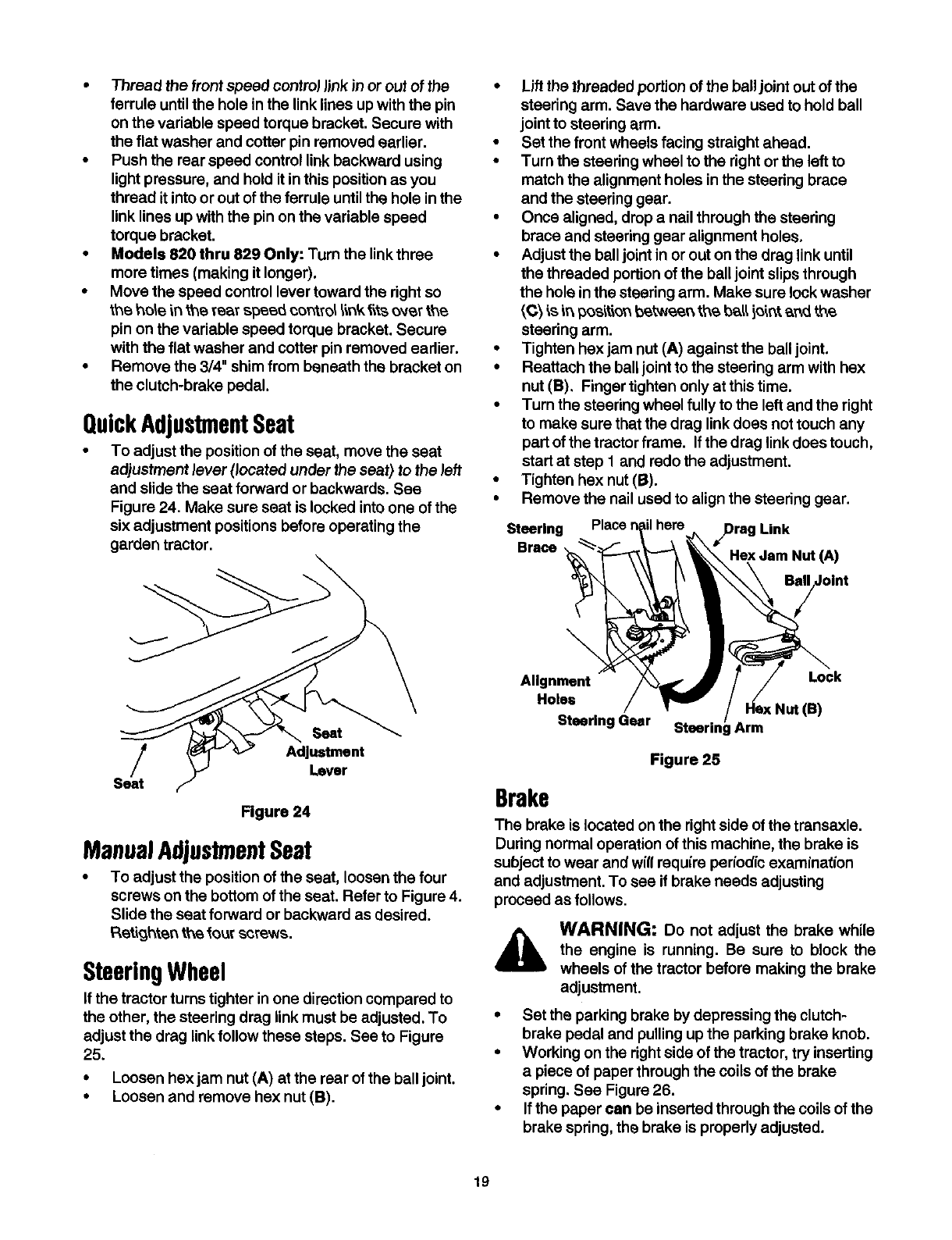
• Lift the threaded portion of the ball joint out of the
steering arm. Save the hardware used to hold ball
joint to steering arm.
• Set the front wheels facing straight ahead.
• Turn the steering wheel to the right or the left to
match the alignment holes in the steedng brace
and the steering gear.
• Once aligned, drop a nail through the steering
brace and steering gear alignment holes.
• Adjust the ball joint in or out on the drag link until
the threaded portion of the ball joint slips through
the hole in the steering arm. Make sure lock washer
_C_is _ p_s'_t'_n_t_eer_ tt,,e ba_ i_ir_t_r_ the.
steering arm.
• Tighten hex jam nut (A) against the balljoint.
• Reattach the balljoint to the steering arm with hex
nut (B), Finger tighten only at this time.
• Turn the steering wheel fully tothe left and the right
to make sure that the drag link does not touch any
part ofthe tractor frame. If the drag linkdoes touch,
start at step 1 and redo the adjustment.
• Tighten hex nut (B).
• Remove the nail used to align the steering gear.
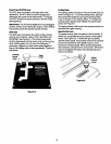
Steering Place 7 here Link
Brace
Hex Jam Nut (A)
Seat
Adjustment
Lever
Seat
Figure 24
ManualAdjustmentSeat
• To adjust the position of the seat, loosen the four
screws on the bottom ofthe seat. Refer to Figure 4.
Slide the seat forward or backward as desired.
Ret'_o,_hte_tt\e four screws.
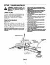
SteeringWheel
If the tractor turnstighter inone direction compared to
the other, the steering drag linkmust be adjusted. To
adjust the drag linkfollow these steps. See to Figure
25.
• Loosen hex jam nut (A) at the rear of the ball joint.
• Loosen and remove hex nut (B).
\
Alignment Lock
Holes
t (e)
Steering Gear Arm
Figure 25
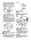
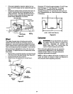
Brake
The brake is located on the right side of the transaxle.
During normal operation of this machine, the brake is
subject to wear and will require periodic examination
and adjustment. To see if brake needs adjusting
proceed as follows.
WARNING: Do not adjust the brake while
the engine is running. Be sure to block the
wheels of the tractor before making the brake
adjustment.
• Set the parking brake bydepressing the clutch-
brake pedal and pulling up the parking brake knob.
• Working on the rightside of the tractor, try inserting
a piece of paper through the coils of the brake
spring, See Figure 26.
• If the paper can be inserted through the coilsof the
brake spring, the brake is properly adjusted.
19