


9
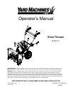
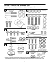
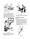
Figure 11
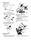
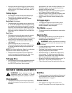
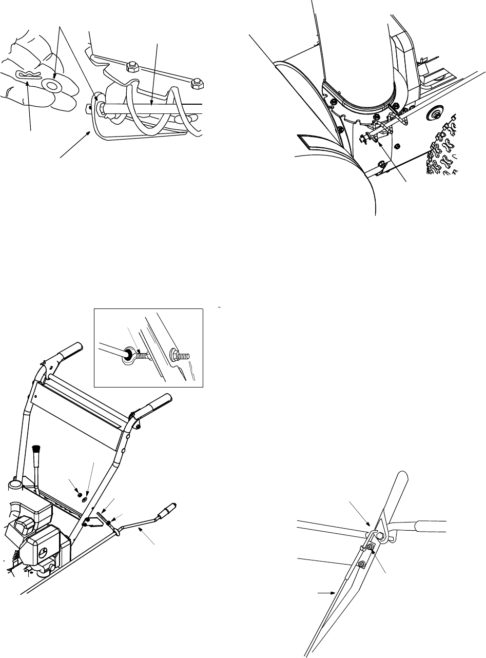
• Thread one hex nut (D) onto the eyebolt on the
chute directional control assembly until there is at
least two inches of threads showing between the
nut and the eyebolt head. See Figure 12 inset.
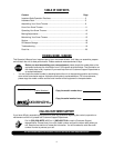
• Place the eyebolt into the hole located half way up
the left handle. See Figure 12. Secure with cupped
washer (N) and hex nut (D) making sure that the
cupped side of the washer is against the handle.
Figure 12
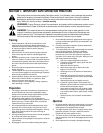
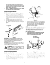
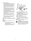
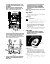
• Adjust the chute directional control bracket so that
the spiral on the chute directional control fully
engages the teeth on the chute assembly. See
Figure 14. Tighten all hardware.
Figure 13
• Check to make sure all nuts and bolts on the control
panel and all four bolts which secure the handles to
the frame are tight.
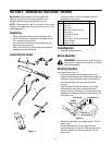
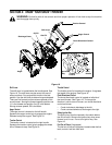
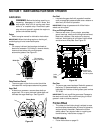
Final Assembly & Adjustments
Auger Control
• To check the adjustment of the auger control, push
forward on the left hand clutch grip (depress the
rubber bumper). There should be slack in the cable.
Release the clutch grip. The cable should be
straight. Make certain you can depress the auger
control grip against the left handle completely.
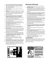
• If necessary, loosen the hex lock nut and thread the
cable in (for less slack) or out (for more slack) as
necessary. Refer to Figure 14.
• Tighten the lock nut against the cable when correct
adjustment is reached.
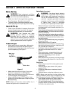
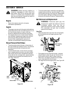
Figure 14
Flat
Washers T
Chute
Directional
Hairpin Clip S
Chute Directional Control
Bracket
Control
Chute
Directional
Control
Eye Bolt
Cupped
Washer N
Hex Nut D
2” of thread
Hex Nut D
Spiral should engage
teeth of chute here
“Z” Fitting
Hex Bolt
Cable