


8
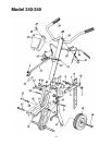
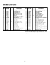
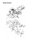
Model 345
1. Attach spark plug wire to spark plug. Make
certain the metal loop on the end of the spark
plug wire (inside the boot) is fastened securely
over the metal tip on the spark plug.
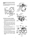
2. Make certain all controls are in the neutral
position (released). (See Figure 8).
3. Place the engine speed control in the START
position.
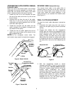
4. Push primer two (2) or three (3) times (see
Figure 9). Wait about two (2) seconds between
each push.
NOTE:
Primer may be needed to restart a warm
engine after a short shutdown.
5. Stand at side of tiller. Grasp the starter handle
and pull out slowly, until it pulls slightly harder.
Let rope rewind slowly.
6. Pull rope with a rapid full arm stroke. Do not
allow handle to snap back. Allow it to rewind
slowly while keeping a firm hold on the starter
handle.
NOTE:
If engine fails to start after three (3) pulls,
push primer two (2) times and pull starter rope again.
7. Repeat steps 4 and 5 until engine starts. Refer
to engine manual for additional engine
information.
NOTE:
After starting engine and prior to using the
tiller, be certain to check the clutch adjustment as
described in “Checking the Clutch Adjustment”
section of the Assembly Instructions.
TO STOP ENGINE
1. Move throttle control lever to STOP or OFF
position.
2. Disconnect spark plug wire from spark plug and
ground against the engine to prevent accidental
starting while equipment is unattended.
HOW TO USE YOUR TILLER
Your tiller is a precision built machine designed for
seed bed preparation, cultivating, furrowing and
mulching. It is engineered to minimize the hardest
work in the vegetable or flower garden, to till the soil
for planting and cultivating, and to perform many
other useful labor saving tasks in the garden. With
the proper amount of care and maintenance, this
machine will provide the owner with many years of
service.
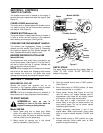
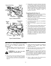
WHEEL POSITION
The tiller is shipped with the wheels adjusted such
that the unit sits level. While tilling, as the tines
enter the ground and the front of the tiller lowers,
the wheels must be raised to level the unit, which is
essential for proper engine operation. This
adjustment is made by removing the clevis pin and
hairpin clip from wheel yoke, raising the wheels to
the desired height, and replacing the clevis pin and
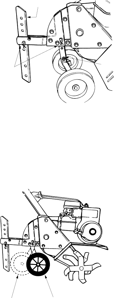
hairpin clip. (See Figure 10.)
Figure 10
CONTROLLING SPEED AND TILLING
DEPTH
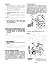
1.
Wheel Yoke Adjustment:
Place wheel yoke so
that the wheels are forward (nearest point
between wheels and tines) for shallow tilling,
cultivating and transport. The forward speed will
increase. Turn yoke around (farthest point
between wheels and tines) for deep tilling.
Forward speed will decrease. (See Figure 11.)
Figure 11
Wheel
Yoke
Depth Stake
Hairpin
Clip and
Clevis Pin
Wheel Yoke in this
position for
deep tilling.
Wheel Yoke in this
position for shallow tilling,
cultivating, and transport.