


5
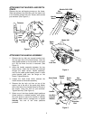
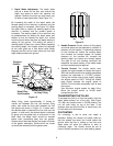
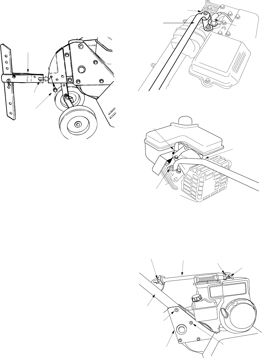
ATTACHING THE TAILPIECE AND DEPTH
STAKE
Remove the two self-tapping screws on the frame.
Slide the tailpiece into the frame, with the lower hole
in the tailpiece toward the front. Secure with screws
just removed. (See Figure 3.)
Figure 3
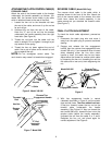
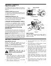
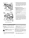
ATTACHING THE HANDLE ASSEMBLY
1. Remove the hex bolt and cupped washer from
the top right side of the frame halves. Hold the
cable guide bracket on the left side of the frame
as it will fall when the bolt is removed. (See
Figure 5.)
2. Insert the handle assembly between the two
frame halves. Insert the hex bolt just removed
through the frame halves, handle assembly,
and into the cable guide bracket (notch in cable
guide bracket goes over the flange on the
frame). Tighten securely.
3. Loosen the hand knob which secures the
handle brace to the handle assembly.
4. Remove the hex lock nut from on top of the
engine, just to the left of the spark plug. Attach
the curved end of the handle brace to the top of
the engine, using hex lock nut just removed.
Tighten securely. (See Figure 4.)
5. Select one of the three handle height positions
(three notches in welded bracket), and tighten
the hand knob to secure the handle in desired
position. Make certain carriage bolt is seated
securely
into one of the three positions
provided.
Figure 4
Figure 5
Tailpiece
Lower
Hole
Self-Tapping
Screw
Hex
Lock Nut
Spark
Plug
Handle
Brace
Models 340 & 390
Model 345
Handle
Brace
Hex
Lock Nut
Spark
Plug
Hand Knob
Handle
Brace
Hex
Lock Nut
Handle
Hex Bolt
Cupped
Washer
Frame
Half
Shoulder
Bolt
Spark
Plug