


SECTION 3
INSTALLATION AND INITIAL TURN-ON
PV-30208 Photovoltaic Inverter
Operation and Maintenance Manual
Copyright 2003, Xantrex Technology Inc.
DOCUMENT: 151315
3-2
noitanimreTGWAegnaReriW
)CA(kcolBnoitubirtsiD2#-0/2
)CD(kcolBnoitubirtsiD2#-0/2
The following table shows acceptable wire gauges to be connected to the PV-30208 AC and DC
inputs.
Wire Gauge Table
All wiring methods shall be in accordance with the National Electrical Code ANSI/
NFPA 70. All power conductors interfacing to the PV-30208 should be sized in
accordance with the National Electric Code ANSI/NFPA 70 and local codes. Large
gauge wire must have a minimum bend radius dependent upon the wire gauge
(refer to the National Electric Code, Article 373-6B). Take care to keep the wire
bundles away from any sharp edges which may damage wire insulation over time.
Xantrex Technology recommends using No. 2 AWG, 105 degrees C, minimum,
copper wire for all connections with the PV-30208.
CAUTION
INSTALLATION INSTRUCTIONS
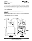
Ventilation Considerations
Check with applicable installation standards for additional clearance requirements.
Installation
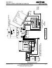
The PV-30208 is designed to be both floor mounted, or wall mounted. The following procedures de-
scribes mounting instructions for both mounting methods.
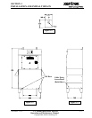
Floor Mounted
1. Move the PV-30208 into place. Lift the PV-30208 from beneath the lower enclosure with a forklift
as shown in Figure 3-2. (See following page.)
2. Anchor the lower enclosure feet to the floor with 1/2” anchor bolts.
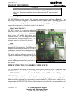
Wall Mounted
1. Screw two 3/8” x 3-1/2” long lag bolts into existing studs in the wall (16-inch mounting center) at
lower mounting level on PV-30208. Lag bolts should be horizontally level with each other. Leave
a minimum of 1” of bolt protruding from the wall.
2. Place the PV-30208 bottom mounting ears, shown in Figure 3-1 and Figure 3-2 onto installed lag
bolts. (See following page.)
3. Hold the unit against the wall and install the upper lag bolts (3/8” x 3-1/2”). Tighten the bolts
firmly.
4. Tighten the lower lag bolts while the unit is held in place.
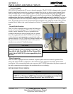
5. Two access panels on the lower enclosure are provided for cable entry, shown in Figure 3-3. (See
following page.)
6. Local building codes may require additional support/reinforcement when wall mounting the PV-
30208. Check with local authorities for further detail.