


SECTION 3
INSTALLATION AND INITIAL TURN-ON
PV-30208 Photovoltaic Inverter
Operation and Maintenance Manual
Copyright 2003, Xantrex Technology Inc.
DOCUMENT: 151315
3-5
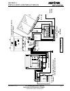
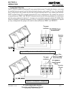
The following wires for connecting the PV-30208 to external devices are not provided by Xantrex
Technology: (See wiring diagram on page 3-6.)
• 3-Phase 208 VAC inverter output to terminals of the 208 VAC primary side of isolation trans-
former. The neutral must be left floating. Ground loops will exist when the inverter starts
switching, which will cause the inverter to shut down due to phase over-currents and will
result in damage to the PV-30208. Also, insure that this neutral is not bonded to the isola-
tion transformer frame.
• System electrical ground to the isolation transformer chassis ground.
• Isolation transformer grid side terminals to line circuit breaker (or the AC disconnect switch if
present).
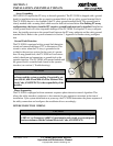
• PV frame ground to PV-30208 enclosure chassis ground stud.
• PV-30208 enclosure chassis ground stud to the electrical distribution system ground.
• PV+ to the inverter enclosure terminal block TBDC+.
• PV- to the inverter enclosure terminal block TBDC-.
• PV neutral if connecting a bipolar PV array.
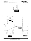
Install all wires listed above. Refer to the following wiring diagram and the system schematics in
Section 7 for more detailed terminal locations.