


9
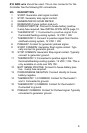
#18 AWG wire should be used. The in-line connector for the
Controller has the following DC connections.
NO. DESCRIPTION
1 START: Generator start signal contact.
2 STOP: Generator stop signal contact.
3 GENERATOR DC HOUR METER.
4 RESERVED (Future ignition lock-out).
5 POWER POSITIVE: Connect to house battery positive.
2-amp fuse required. See INSTALLATION NOTE page 10.
6 THERMOSTAT 1: Connected to positive signal from
thermostat/heating-cooling system, 12 VDC = ON.
7 THERMOSTAT 2: Connect to positive signal from thermo-
stat/heat-cooling system, 12 VDC = ON.
8 PREHEAT: Contact for generator preheat signal.
9 START COMMON: Generator Start signal contact. Typi-
cally connect to generator ground.
10 STOP COMMON: Generator Stop signal contact. Typically
connect to generator ground.
11 THERMOSTAT 3: Connected to positive signal from
thermostat/heating-cooling system, 12 VDC = ON. This is
only available on units over S/N 150.
12 BATT SENSE POSITIVE: Connect to house battery posi-
tive. 2-amp fuse required.
13 POWER/SENSE NEGATIVE: Connect directly to house
battery negative.
14 THERMOSTAT 1,3 COMMON: Contact for thermostat 1
and 3. Connected to ground.
15 THERMOSTAT 2 COMMON: Contact for thermostat 2.
Connected to ground.
16 PREHEAT COMMON: Contact for Preheat signal. Typically
connected to generator ground.