


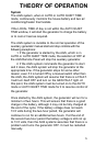
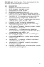
10
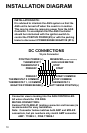
START
START COMMON
POSITIVE POWER (+)
BATT SENSE POSITIVE(+)
NEGATIVE POWER/SENSE(-)
THERMOSTAT 1
THERMOSTAT 2
THERMOSTAT 1, 3 COMMON
THERMOSTAT 2 COMMON
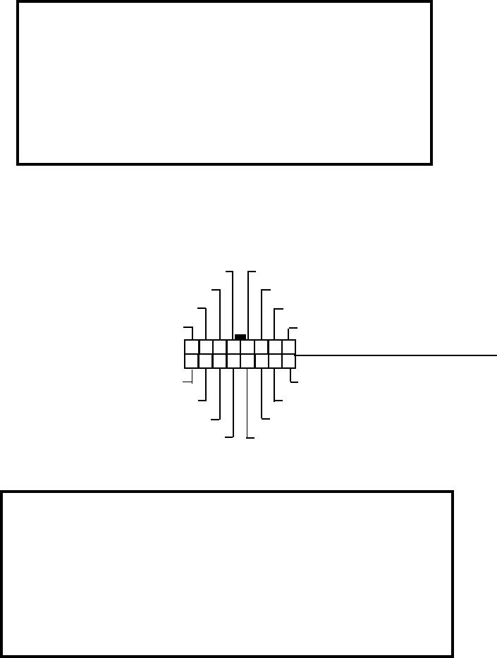
DC CONNECTIONS
16 pin Connector
STOP
GEN HOUR METER
8 7 6 5 4 3 2 1
16 15 14 13 12 11 10 9
PREHEAT
PREHEAT
STOP COMMON
THERMOSTAT 3
INSTALLATION NOTE:
It is advised to interlock the AGS system so that the
AGS unit is turned off when the coach is in motion.
This may be done by removing power from the AGS
Controller. To accomplish this the AGS Controller
should be interlocked with the ignition switch to
control the POSITIVE POWER (#5) or with the parking
brake to disconnect POWER/SENSE NEGATIVE (#13).
Connector view is looking into the AGS CONTROLLER.
All wires should be #18 AWG
MATING CONNECTORS:
Xantrex P/N 76-0090-01 (mating connector and harness) is
recommended for easy installation.
Note: Connector below matches both AMP and MOLEX
connectors, but pin numbers only match AMP connector.
AMP: 770583-1, PINS 770988-1
INSTALLATION DIAGRAM
RESERVED(FOR IGN. LOCK-OUT)