


19 20
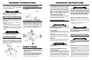
ASSEMBLY INSTRUCTIONS
The mower will attach to most tractors with a Category
I, 3 pt. hitch system and a 540 RPM PTO. Do not exceed
horsepower recommendations.
DANGER!
Operating with PTO speed over 540 RPM can cause
excessive vibration and mower failure, which can
result in serious injury or even death.
CAUTION!
Always use personal protection devices such as
eye and ear protection during assembly.
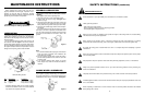
A-FRAME ATTACHMENT
Refer to the “exploded views” of this manual and figure
1. Attach the rear brace bars (1) to the lugs on the rear of
the deck with the correct hardware. Attach the A-Frame
bars (2) to the lugs on the front of the deck. Connect the
upper ends of the A-Frame bars with the rear brace bars
and swinging top link clevis together with the M12 bolt,
washers, spacer and locknut.
DRIVELINE TO MOWER
GEARBOX ATTACHMENT
1. Grab and turn the yoke collar of the driveline end to be
attached to the gearbox. Note: Make sure that you
connect the driveline end with the male shield
tube to the mower.
2. Slide the yoke with the collar turned onto the mower’s
gearbox input shaft. Note: Make sure that the plastic
protective cone is mounted on the gearbox.
3. Move yoke back and forth until its locking pin has
engaged on the gearbox input shaft groove.
3 PT. HITCH ATTACHMENT
Remove bolt from hitch point location and assemble as
shown in figure 2.
Figure 1
Figure 2
CASTER WHEEL ATTACHMENT
Figure 3
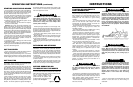
DEALER SET-UP INSTRUCTIONS
Assembly of this mower is the responsibility of the
dealer.The mower should be delivered to the owner com-
pletely assembled, lubricated and adjusted for normal
cutting conditions.
Set-up mower as received from the factory with these
instructions.
• Remove mower from crate.
• Complete assembly of factory pre-assembled hitch.
• Refer to parts lists and exploded view drawings for
more details.
• To complete assembly, it will be easier if components
are aligned and assembled loosely before tightening
hardware.
Some mowers will be supplied with all four wheels fully
assembled. However, for models that do require
assembly, please follow these instructions. Install two
3
/
4
”
spacers on each fork and wheel assembly shaft. Insert
fork shaft into axle arm weldment. Additionally install two
3
/
4
” and two
3
/
8
” spacers on each axle shaft and retain
using the snapper pins supplied. See figure 3.
CUTTING HEIGHT ADJUSTMENT
Important: Avoid very low cutting heights.Striking the
ground with the blades gives the most damaging shock
loads a mower can encounter and will cause damage to
it and the driveline.
1. Using the tractor, raise the mower off the ground and
place supports underneath of it, so that it will not drift
downwards while making adjustments or mainte-
nance.
2. While supporting the wheel and yoke assembly off the
ground, remove the snapper pin from the top of the
gauge wheel spindle. Position the supplied spacers
as required for achieving the desired cutting height.
3. Make sure all four wheels are adjusted the same.
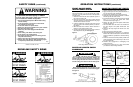
TRACTOR PREPARATION
Do not install mower on a tractor over 40 HP.
The safe operation of this mower is the responsibil-
ity of the operator. Only qualified people familiar with
this manual should operate this machine. The operator
should be familiar with the machine, tractor and all safe-
ty practices before starting operation. This mower is
designed for lawn and grass mowing. It is not
designed for rough conditions or heavy weed
mowing. The mower is equipped with suction type
blades, which are best suited for lawn mowing.
Always operate tractor at 540RPM.
This chapter provides information for attaching mower
to tractor and preparing it for field operation. Review this
data prior to tractor hookup and operation.
WHEEL TREADS
Tractor wheel tread spacing should be increased when
working on inclines or rough ground to reduce the possi-
bility of tipping.
STABILIZER BARS AND SWAY BLOCKS
Use stabilizer bars or sway blocks to prevent side sway
of the mower.
DRAWBAR
Shorten or remove the tractor drawbar so it will not inter-
fere with the up and down movement of the mower.
DRIVELINE ATTACHMENT TO TRACTOR
1. Grab and turn the collar on the end of the attaching
yoke.
2. Slide yoke with the collar turned onto the tractor PTO
shaft.
3. Move yoke back and forth until its locking pin has
engaged on the PTO shaft groove.
ATTACHING THE MOWER TO TRACTOR
(LIFT TYPE ONLY)
This mower is designed for tractors with 540 RPM and
category I hitch. Back the tractor up to the mower so that
the lower draft arms are in alignment with the mower lift
pins. Stop the engine, lock the brakes or place the tractor
in park. Connect the tractor and stabilizer bars to the
lower lift pins. Adjust the top link so it will pin to the top
holes in the A-Frame or into holes in floating top link.
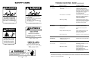
WARNING!
Do not operate tractor with less than 20% of it’s
gross unballasted mass on the front wheels with the
mower in the transport position.
WARNING!
When attaching the driveline yoke to the tractor PTO
shaft, it is important that the spring activated locking
collar turns freely and that it seats properly in the
tractor PTO shaft groove.
WARNING!
Avoid personal injury! Be sure tractor engine is off,
that key is removed from ignition and allow blades to
completely stop turning before dismounting to make
adjustments.
WARNING!
Do not get between tractor and mower when the
engine is running.
DANGER!
Never allow children to operate, ride or come close
to the mower or tractor. Usually, 15-16 year old chil-
dren who are mature and responsible can operate
the mower with reasonable safety if they have read
the operator’s manual, been trained in safe operation
of the machine, and are physically large and strong
enough to reach and operate the controls easily.
OPERATION INSTRUCTIONS