


17 22
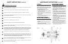
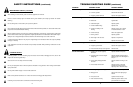
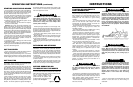
WARNING
To prevent serious injury or death:
Si no lee ingles, pida ayuda a alguien que si lo lea para
que le traduzca las medidas de seguridad.
• Read and understand Operator’s Manual before using.
Review annually.
• Do not permit riders on the tractor or mower. Never
carry children on tractor seat.
• Do not allow children to operate mower.
• Operate only with guards installed and in good condition.
• Keep away from moving parts.
• Operate only with tractor equipped with ROPS and
seatbelts.
• Before mowing, clear debris from mowing area.
• Do not operate in the raised position.
• Stop engine, set brake and wait for all moving parts to
stop before dismounting.
• Support mower securely before working beneath unit.
• Transport with clean reflectors, SMV and working lights
as required by federal, state, and local laws.
M100
ITEM 9 – Part No. 101157
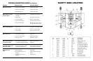
SAFETY SIGNS (continued)
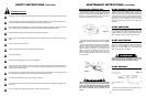
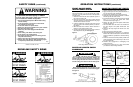
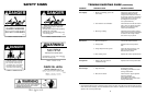
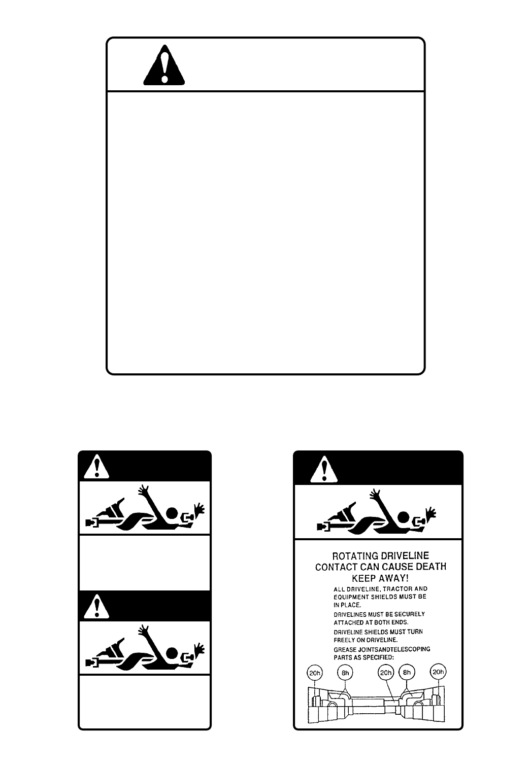
DRIVELINE SAFETY SIGNS
DANGER
SHIELD MISSING
DO NOT OPERATE
DANGER
SHIELD MISSING
DO NOT OPERATE
DANGER
WARNING!
A loose shaft could slip off and result in personal
injury or damage to the mower. When attaching the
driveline yoke to the tractor PTO shaft, it is important
that the spring activated twist collar turns freely and
that the locking pin is seated on the PTO shaft groove.
WARNING!
Before operating the mower check to make sure the
driveline will not bottom out or become disengaged.
See figure 6.
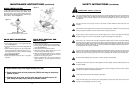
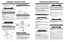
Figure 5
Front Gauge Wheel Clearance
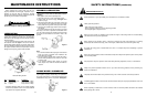
Figure A Figure B
Figure C Figure D
Figure 6
Driveline in maximum compressed position
ADJUSTING DRIVELINE LENGTH
1. Slide the driveline together until it “bottoms out.”
2. Apply colored tape to the inner plastic shield tube
1
/
8
”
from the end of the outer shield tube.
3. Reconnect the driveline to the tractor PTO shaft.
4. Raise the mower to full transport position or until the
driveline just hits the deck at front.
5. If the distance between colored tape and outer shield
tube is 1
9
/
16
” or less, the metal drive tubes
should be shortened per figure A.
6. Shorten the male and female plastic shield tubes
equally. See figure B.
7. The metal drive tubes also have to be shortened in
the same length as the plastic shield tubes. See
figure C.
8. Round off all sharp edges and remove burrs. See
figure D.
9. Apply grease to the metal drive tubes.
10. There should always be a minimum of 1
9
/
16
” clearance
between the male and female drive and shield tubes
when the driveline is operated in its shortest working
position.
11. Lower the mower to the lowest position possible and
check the distance of the colored tape to the end of
the outer shield tube.
12. Driveline tube engagement or overlapping must
always exceed 12”.
13. If tubes do not overlap by 12” or more, consult with
your dealer to obtain a longer driveline.
FRONT GAUGE WHEEL
INTERFERENCE CHECK
Do not operate the mower until this interference check
has been performed. If you use the mower with a differ-
ent tractor, you must perform the check for that particular
mounting again.
1. Raise the mower with the tractor hydraulic system to
the maximum height of lift.
2. Pivot both of the mower front gauge wheels forward
and check that there is clearance between the gauge
wheels and the tractor’s rear tires.
3. If there is interference, lower the mower to the ground
and move hitch to the extended position (see assem-
bly chapter).
4. Move the tractor tires inward to obtain clearance or
lower the mower until clearance exists.
5. Set the 3-point quadrant stop so the mower cannot be
raised beyond the set point. See figure 5.
DRIVELINE LENGTH CHECK
PROCEDURE
OPERATION INSTRUCTIONS (continued)